Technical specifications
9.7 KP8F – Encoder evaluation of the fail-safe channels
KP8, KP8F, KP32F
Operating Instructions, 11/2011, A5E03284305-02
117
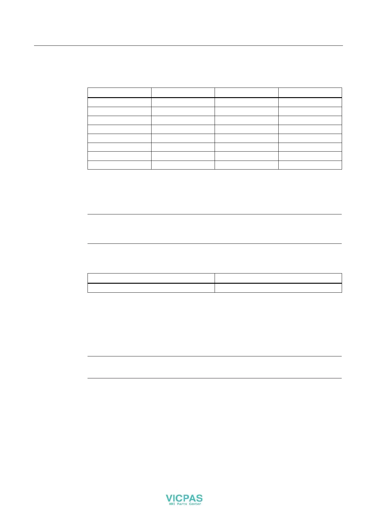
For the output bytes 0 to 2, the bit combinations of the bit x are illustrated in the following
table.
Bit R x (red, byte 0) Bit G x (green, byte 1) Bit B x (blue, byte 2) LED
1 0 0 Red
0 1 0 Green
0 0 1 Blue
1 1 0 Yellow
1 1 1 White
0 0 0 OFF
1 0 1 OFF
0 1 1 OFF
9.7 KP8F – Encoder evaluation of the fail-safe channels
Note
For digital inputs that are reserved with a fail-safe channel, the process image described in
the chapter "KP8 and KP8F - Bit assignment in the proces
s image (Page 116)" is not used.
The fail-safe channels occupy the following address areas in the process image of the fail-
safe controller:
Input area Output area
x + 0 to x + 4 x + 0 to x + 3
x The start address for the input and output range.
The address was entered on the "Addresses" tab in the HW Config in the object
properties of the module "KP8F, Slot 2".
The first byte in the process image describes the switch state of the connected sensors or a
connected EMERGENCY-OFF button. The setting is described in the section "KP8F –
Setting the fail-s
a
fe properties (Page 77)".
Note
The unused bits in the byte 0 are always "0".