Mounting and connecting the HMI device
4.4 Connecting the HMI device
KP8, KP8F, KP32F
Operating Instructions, 11/2011, A5E03284305-02
51
● Use equipotential bonding conductors made of copper or galvanized steel. Establish a
large surface contact between the equipotential bonding conductors and the
grounding/protective conductor and protect them from corrosion.
● Use a suitable cable clip to clamp the shield of the data cable flush to the equipotential
bonding rail. Keep the length of cable between the HMI device and the equipotential
bonding rail as short as possible.
● Route the equipotential bonding conductor and data cables in parallel and with minimum
clearance between them.
Procedure
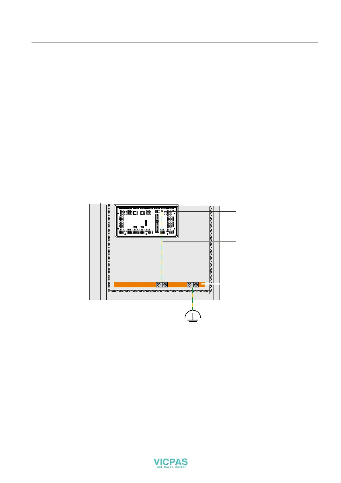
1. Connect the functional grounding of the control cabinet according to the following figure.
Cable shielding is not suitable for functional grounding.
Note
Interface blocks may be damaged or destroyed if the cable for the functional ground does
not meet the required minimum cross-section according to the following figure.
&RQQHFWLRQIRUWKHIXQFWLRQDO
JURXQGLQJ
&DEOH
FURVVVHFWLRQDWOHDVWPP
2
%XVEDU
&DEOH
FURVVVHFWLRQDWOHDVWPP
2