Mounting and connecting the HMI device
4.4 Connecting the HMI device
KP8, KP8F, KP32F
56 Operating Instructions, 11/2011, A5E03284305-02
Procedure
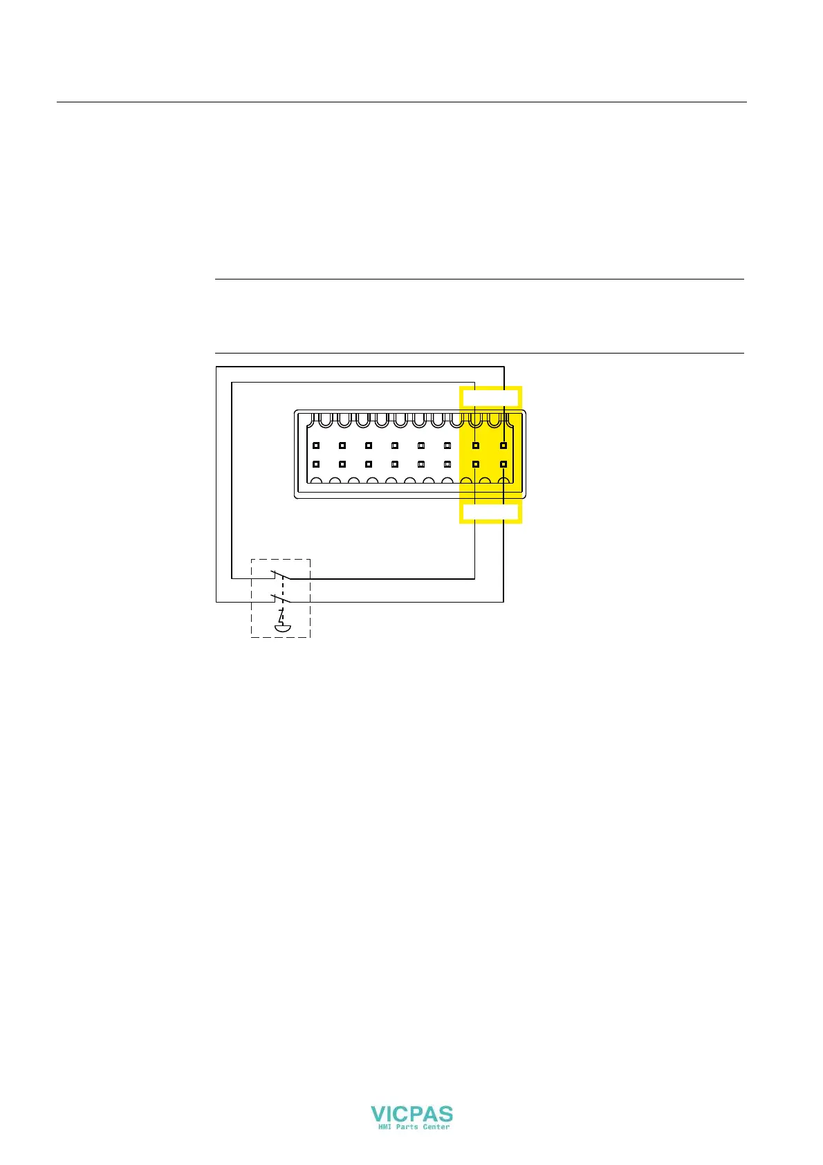
1. Connect the EMERGENCY-STOP button as follows to the connector for the fail-safe
digital inputs:
– Sensor supply VS.0 for the FI.0 input
– Sensor supply VS.1 for the FI.1 input
Note
The assignment of the fail-safe inputs has changed as of product version 03.
External power supply is not permissible for VS.0 and VS.1.
(PHUJHQF\6WRSEXWWRQ
0 ,20 ,2,2,2
/ ,2 / ,2 ,2,2
),),
9696
The EMERGENCY-STOP button must be connected as an equivalent break contact.
Observe the affiliated setting for "Evaluation of the sensor" in the HW config - see section
"KP8F – Setting the fail-safe properties (Page 77)".