Mounting and connecting the HMI device
4.4 Connecting the HMI device
KP8, KP8F, KP32F
Operating Instructions, 11/2011, A5E03284305-02
59
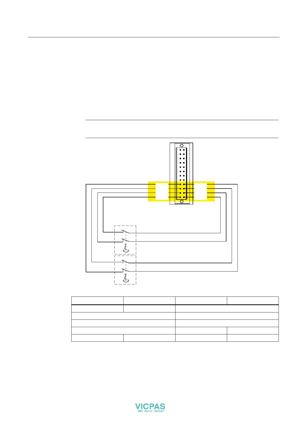
Procedure
1. Connect the EMERGENCY-STOP button as follows to the connector for the fail-safe
digital inputs:
– Sensor supply VS.0 for the FI.0 input
– Sensor supply VS.1 for the FI.1 input
– Sensor supply VS.2 for the FI.2 input
– Sensor supply VS.3 for the FI.3 input
Note
External supply is not permitted for VS.0, VS.1, VS.2 and VS.3.
(PHUJHQF\VWRSEXWWRQ
(PHUJHQF\VWRSEXWWRQ
,2
,2
,2
,2
,2
,2
,2
,2
,2
,2
,2
,2
,2
),
,2
,2
),
),
),
96
96
96
96
,2
;
The following connection options are available:
FI.0 FI.1 FI.2 FI.3
1oo1 1oo1 Not connected
1oo2 Not connected
1oo2 1oo2
1oo2 1oo1 1oo1
1oo1 1oo1 1oo1 1oo1
The EMERGENCY-STOP button must be connected as an equivalent break contact.
Observe the respective setting for "Evaluation of the sensor" in HW Config - see section
"Setting the fail-safe properties (Page 89)".