5 Project Engineering for the OPC Server
64
Commissioning PC Stations - Manual and Quick Start
Release 5/2005
C79000-G8976-C156-07
5.4 Using Symbols for S7 Connections
Symbol tables are created during project engineering with STEP 7 on a central
engineering station in the form of STI files.
You can continue to use the symbol definitions made in the STEP 7 project
engineering when working with OPC. This is necessary if user applications (OPC
clients) are to access symbolic variables over the OPC server.
The symbol tables used are those of the CPUs for which S7 connections are
planned for the OPC server. Symbols of the symbol table that relate, for example,
to data blocks (DBs), bit memory, inputs, and outputs are taken into account.
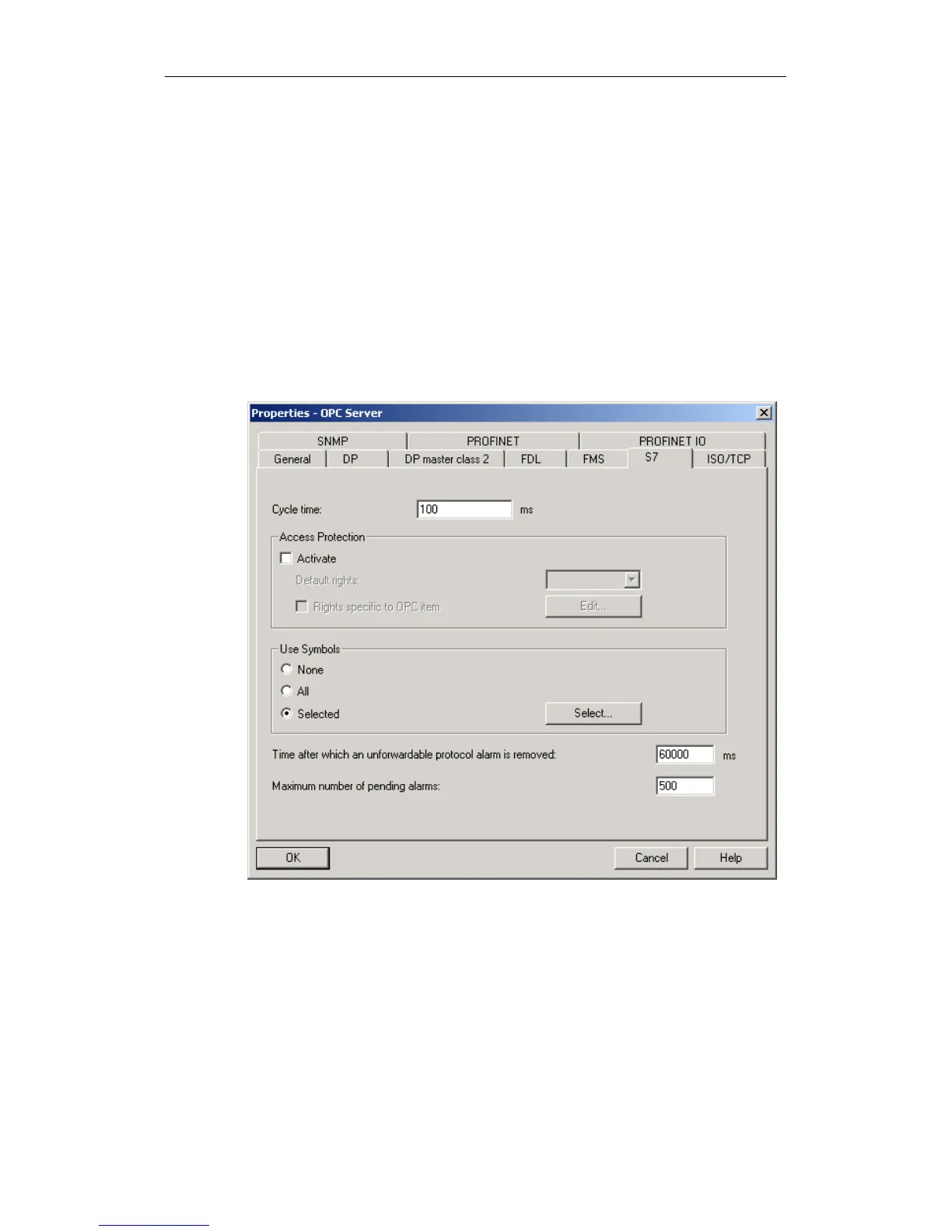
In the “S7” tab of the properties dialog of the OPC server, you can specify which
STEP 7 symbols you want to use on the OPC server.