R 02/92
Programming Instructions
9.4.5 Working Data Block Assignment
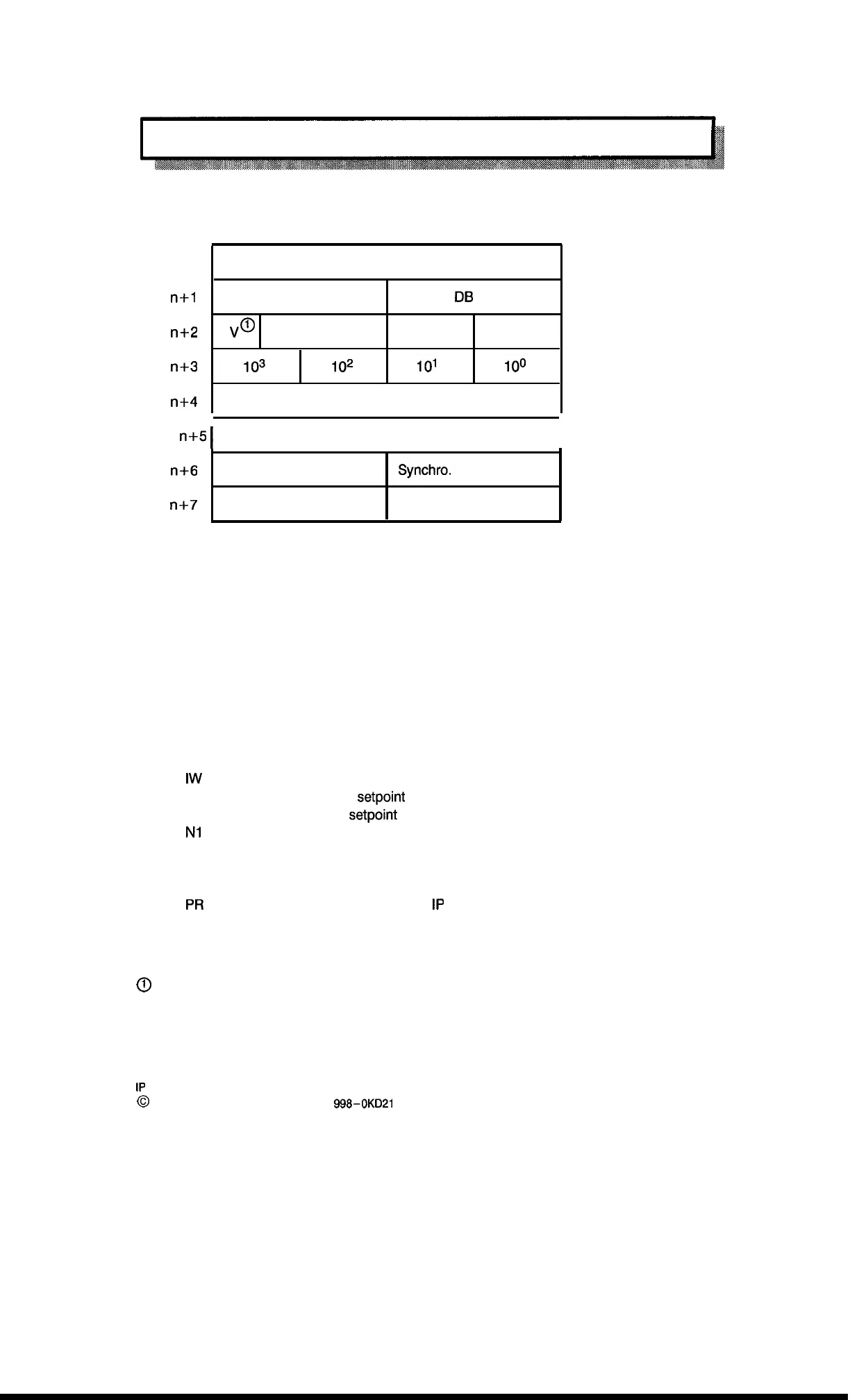
The organization of the parameter list in the working data block is shown below.
DW n
Command
KS
DW
n+l
Track number
User
DB
number
KY
DW
n+2
“o
x
“0”/4
104
KH
DW
n+3
103
102
101
100
KH
DW
n+4
Track identifier bits, channel 1
KM
DW n+5
I
Track identifier bits, channel 2
I
KM
DW
n+6
Assigned
Synchro.
–interrupt info.
KM
DW
n+7
Enable for reset
Number of the alarm bit
KY
The entries shown in bold face boxes in the working data block must be saved during interrupt
processing at the beginning of the interrupt organization block, and reloaded before the interrupt
organization block is exited if function block FB 158 is called from there.
The meaning of the individual entries is explained below.
Data word DW n must be supplied with the desired command from the following command list.
KS = KB
KS = AE
KS = SS
KS = SH
KS =
IW
KS = AW
KS = EW
KS =
N1
KS = N2
KS = IV
KS = IS
KS =
PR
KS = MB
KS = RV
@ V = sign,
Only output of identifier bits and control bits
Change setpoints of one track
Software synchronization
Hardware synchronization
Output of the actual value
Output of the initial
setpoint
Output of the end
setpoint
Read zero shift, channel 1
Read zero shift, channel 2
Inhibit interrupt for supply
Inhibit interrupt
Transfer verify-read number to
1P
Calculate average value
Specify interrupt direction
“O” positive
“1” negative
9 – 33
1P
241 Equipment Manual
@
Siemens AG 1989, Order No.: 6ES5
998-0KD21
Artisan Technology Group - Quality Instrumentation ... Guaranteed | (888) 88-SOURCE | www.artisantg.com

 Loading...


