Programming Instructions
R 02/92
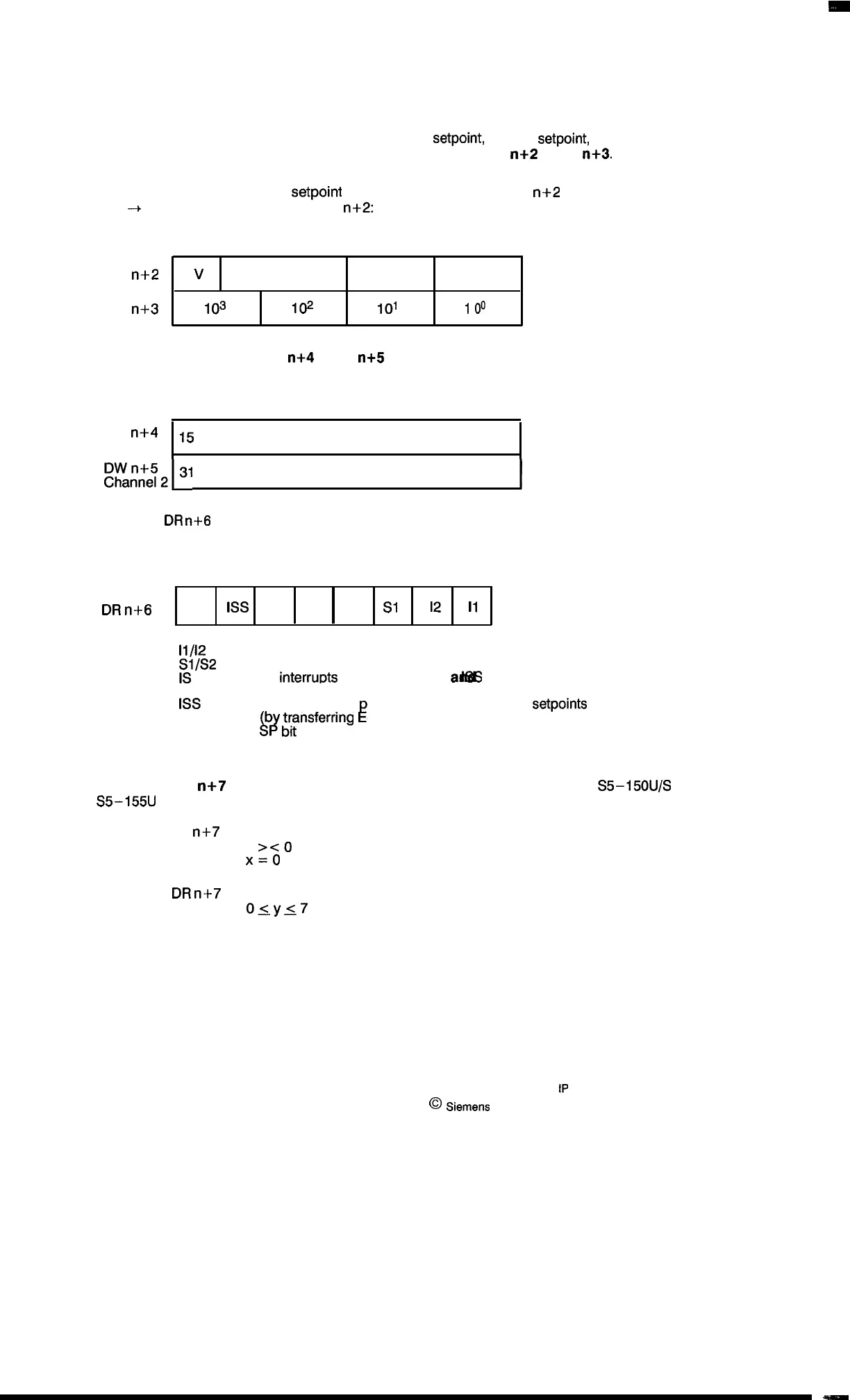
Depending on whether the command parameter (DW n) contains the command “IW”, “AW”,
“EW”,
“N1” or “N2”, either the actual value, the initial
setpoint,
the end
setpoint,
the zero shift of
channel 1 or the zero shift of channel 2 is stored in data word DW
n+2
or DW
n+3.
Any interrupt processing of a
setpoint
is indicated in data word DW
n+2
(setpoint with inter-
rupt
-+ assignment of bits 4 to 7 of DW n+2: 0100 = 4). The bit assignment is shown below.
15
87
0
DW
n+2
v
x
“0”/4
104
DW n+3
103
102
101 I
00
The contents of data word DW
n+4
or DW
n+5
indicate the track identifier bits of channel 1 or 2.
The setup is shown below.
15
87
0
DW
n+4
15
Channel 1
(Track identifier bit)
o
DW n+5
Channe12131
(Track identifier bit)
16
Data word
DR
n+6
contains the synchronization bits, the interrupt bits for each channel and the
status information concerning an alarm inhibit (see operating instructions).
76543210
DR
n+6
SP 1ss
Is –
S2
S1
12
11
11/12
Interrupt in channel 1/2
SJ/s2
Channel 1/2 synchronized
All
interru~ts
inhibited (Bits IS
a4fitf3
are set when E3 is
transferred.)
1ss
Interrupt for sup lying the module with new
setpoints
is inhibited
L?
!
b
~;~nsferring
4).
SP
Data word DW
n+7
must not be supplied unless programmable controller S5–150U/S or
S5–155U
in 150U mode is used.
DL
n+7
Enable for reset
x
><0
No reset
)(=()
Reset applicable alarm bit in the system data
DR
n+7
Number of the alarm bit
osys7
9 – 34
1P
241 Equipment Manual
@
siWWIS
AG 1989, Order No.: 6ES5 998-0KD21
Artisan Technology Group - Quality Instrumentation ... Guaranteed | (888) 88-SOURCE | www.artisantg.com

 Loading...


