R 02/92
Programming Instructions
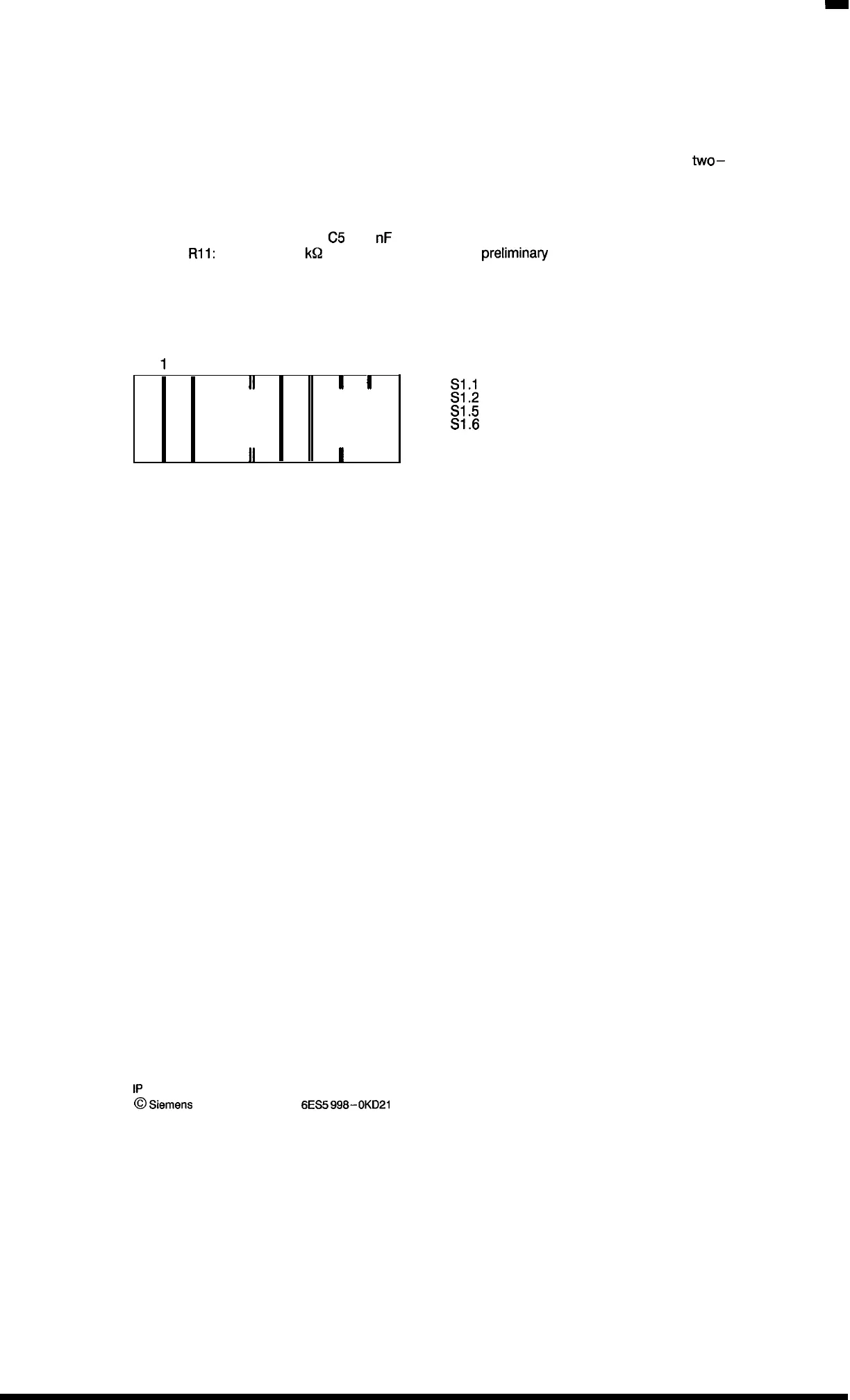
Jumper assignment of the incremental encoder matching module
Assuming that an encoder with a symmetrical line (5 V input voltage) is used (providing
two–
phase displaced pulse sequences) and that the evaluation of two signal edges is selected, then
the following jumpers and components must be soldered in (configuration at delivery):
Solder jumpers:
R4, R6, R7, R9, R12, R14
Capacitors:
Cl, C2,
C5
(1 O
nF
for all)
Resistor
R11:
2.2
kQ
(for a 24 V voltage at the prelimina~ contact)
DIP switch S2.1:
open
DIP switch S1
1
2345678
II II
I I
II II
I
1
S1.1
closed
S1.2
closed
S1.5
closed
S1.6
closed
The encoder matching module is inserted into the slot for channel 1.
1P
241 Equipment Manual
@
.Siemens
AG 1989, Order No.:
6ES5
998-0KD21
9 – 47
Artisan Technology Group - Quality Instrumentation ... Guaranteed | (888) 88-SOURCE | www.artisantg.com

 Loading...


