Optional Configurations
5-8
High Speed Counter Encoder Module User Manual
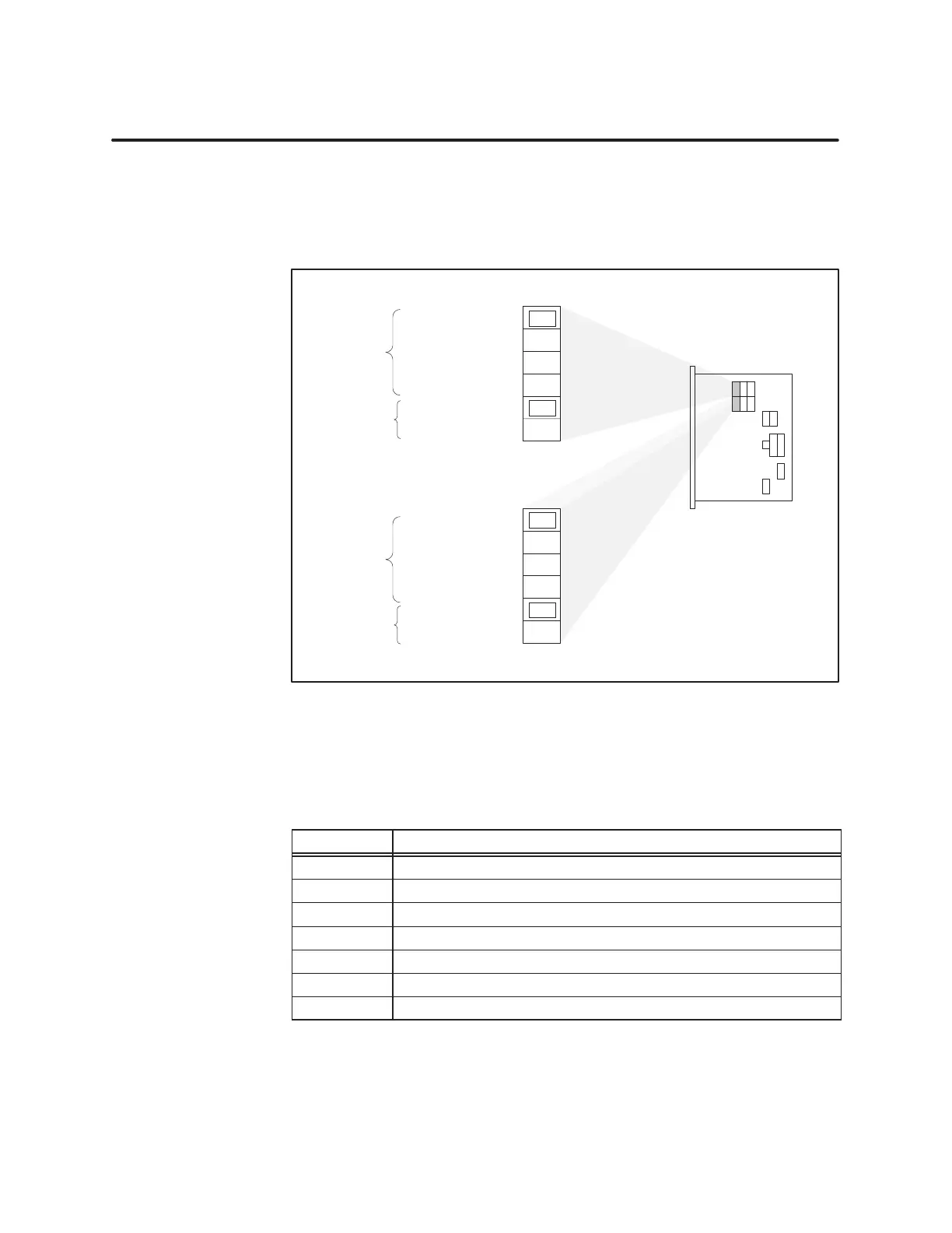
5.5 24-Bit Counter Input Jumper Selection
Figure 5-4
shows the jumpers that select input signals for the 24-bit
counter
. T
able 5-2 defines the input signal names referred to in following
paragraphs. After you select the jumpers, you must program the setup
words and preset words. Jumpers are shown in their default positions.
Input
A pulse
1
s internal pulse
Counter 2 Output
or Counter 3 Output
Input B pulse
or Up Count Only
Input
A
Options:
Input B
Options:
Counter 1
E1
E2
E3
E4
E5
E6
••
••
••
••
••
••
Input
A pulse
1
s internal pulse
Counter 5 output
or Counter 6 output
Input B pulse
or Up Count Only
Input
A
Options:
Input B
Options:
Counter 4
••
••
••
••
••
••
E7
E8
E9
E10
E11
E12
Figure 5-4
24-Bit Counter Input Jumpers
The input signals for each channel are defined in T
able 5-2.
T
able 5-2
Input Signal Names
Input Definition
A Input A: Quadrature, Up Count or Down Count Input
B Input B: Quadrature, Down Count or Count Direction Input
C Input C: Pulse Input or Control
D Input D: Pulse Input or Control
INDEX Count Control, Edge Triggered (24-bit counter only)
INHIBIT Count Control, Edge or Level Triggered (24-bit counter only)
RESET Count Control, Level Triggered (24-bit counter only)