1
1.4 ”SIMODRIVE 611 universal E” control board
1-49
Siemens AG 2005 All Rights Reserved
SIMODRIVE 611 universal Description of Functions (FBU) – 04.05 Edition
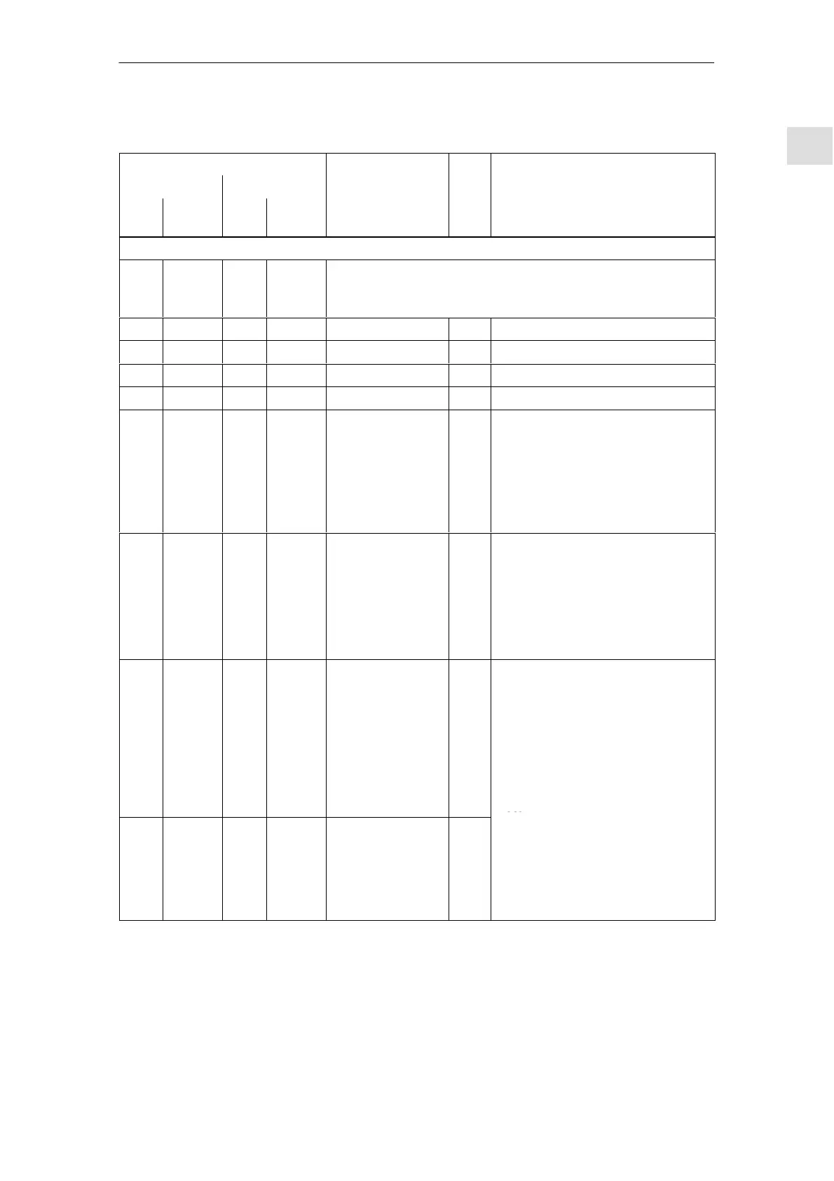
Table 1-6 Overview of the drive–specific terminals, continued
Terminals Technical dataType
1)
Function
Drive A
Technical dataType
1)
Function
Drive B
No.
Technical dataType
1)
Function
Desig-
nation
No.Desig-
nation
Terminals for the analog inputs and digital inputs/outputs (X453, X454)
X453 X454 Connector type: 10–pin conn. strip
Max. conductor cross–section for finely–stranded or solid conduc-
tors: 0.5 mm
2
56.A X453.1 56.B X454.1 none – –
14.A X453.2 14.B X454.2 none – –
24.A X453.3 24.B X454.3 none – –
20.A X453.4 20.B X454.4 none – –
65.A X453.5 65.B X454.5 Controller enable
drive–specific
I Typ. current consumption:
6 mA at 24 V
Signal level (incl. ripple)
High signal level: 15 V to 30 V
Low signal level: –3 V to 5 V
Electrical isolation:
Ref. is T. 19/T. M24
9 X453.6 9 X454.6 Enable voltage
(+24 V)
S Reference: Terminal 19
Maximum current
(for the total group): 500 mA
Note:
The enable voltage (terminal 9) can
be used to supply the enable signals
(e.g. controller enable).
I0.A X453.7 I0.B X454.7 Digital input 0
2)
Fast
input
3)
DI Voltage: 24 V
Typ. current consumption:
6 mA at 24 V
Signal level (incl. ripple)
High signal level: 15 V to 30 V
Low signal level: –3 V to 5 V
Electrical isolation:
Ref. is T. 19/T. M24
Note:
I1.A X453.8 I1.B X454.8 Digital input 1
2)
DI
The parameterization of the input
terminals and the standard as-
signment is described in Chapter
6.4.2.
An open–circuit input is
interpreted as 0 signal.
1) I: Input; S: Supply; DI: Digital input
2) Can be freely parameterized
All of the digital inputs are de–bounced per software. For the signal detection, this results in a delay time
of between 1 and 2 interpolation clock cycles (P1010).
3) I0.x is internally hard–wired to the position sensing function where it acts almost instantaneously.
10.99
 Loading...


