Commands Calling Axis Movements
2.1 Interpolation commands
04.07
2-26
© Siemens AG 2007 All rights reserved
SINUMERIK 802D sl/840D/840D sl/840Di/840Di sl/810D ISO Milling (PGM) -- 04.07 Edition
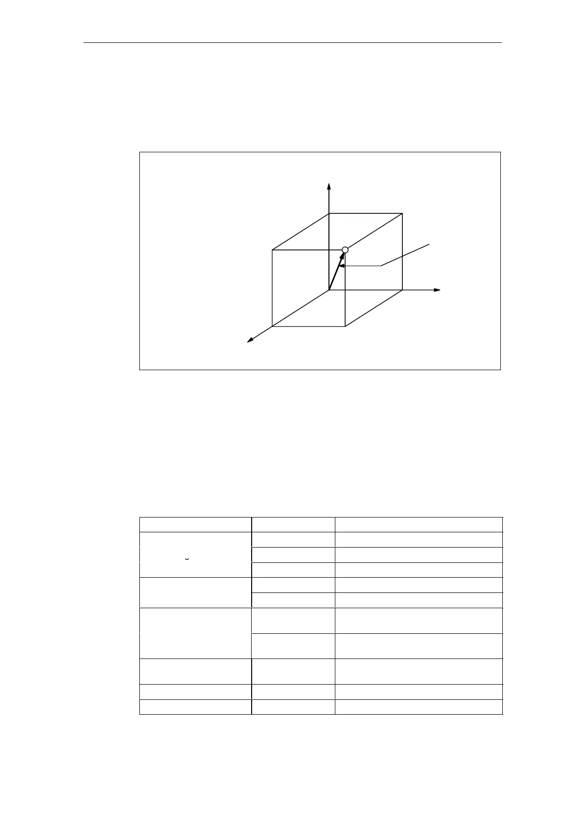
End point
The end point can be specified in either incremental or absolute values. In G code
system B and C it is determind corresponding to the designation of G90 or G91 (for
details, see 3.2.1, “Absolute/Incremental Programming”).
Example of programming
Y-axis
40.
40.
Tangential
velocity
0
Z-axis
X-axis
40.
G01 X40. Y40. Z40. F100;
100 mm/min
Fig. 2-2 Linear interpolation
2.1.3 Circular interpolation (G02, G03)
Command format
To execute the circular interpolation, the commands indicated in Table 2-2 must be
specified.
Table 2-2 Commands necessary for circular interpolation
Item Command Description
G17 Circular arc in the XY plane
Plane designation
G18 Circular arc in the ZX plane
G19 Circular arc in the YZ plane
G02 Clockwise (CW)
Direction o
rotation
G03 Counterclockwise (CCW)
Two axes among
X, Y, and Z
End point position in a workpiece coordi-
nate system
Position o
end point
Two axes among
X, Y, and Z
Signed distance from the start point to
the end point
Distance from the start
point to the center
Two axes among I,
J, and K
Signed distance from the start point to
the center
Radius of circular arc R Radius of circular arc
Feedrate F Velocity along the circular arc

 Loading...


