3-41
© Siemens AG 2007 All rights reserved
SINUMERIK 802D sl/840D/840D sl/840Di/840Di sl/810D ISO Milling (PGM) -- 04.07 Edition
Movement Control Commands
3.1 The coordinate system
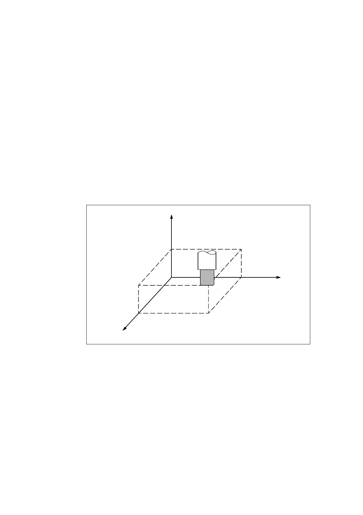
A tool position is clearly determined by coordinates within a coordinate system.
These coordinates are defined by program axes. For example, if there are 3 pro-
gram axes involved designated as X, Y, and Z, the coordinates are specified as:
X... Y... Z...
The above command is called a dimension word.
Z
Y
55.0
30.0
44.0
X
Fig. 3-1 Tool position specified by X... Y... Z...
The following three coordinate systems are used to determine the coordinates:
1. Machine coordinate system (G53)
2. Workpiece coordinate system (G92)
3. Local coordinat e system (G52)
3

 Loading...


