Movement Control Commands
3.1 The coordinate system
04.07
3-56
© Siemens AG 2007 All rights reserved
SINUMERIK 802D sl/840D/840D sl/840Di/840Di sl/810D ISO Milling (PGM) -- 04.07 Edition
3.1.10 Rotatio n o f co o rdinate system (G68, G69)
Does not work with SINUMERIK 802D sl.
Using the G68 and G69 commands
Features of G68 and G69
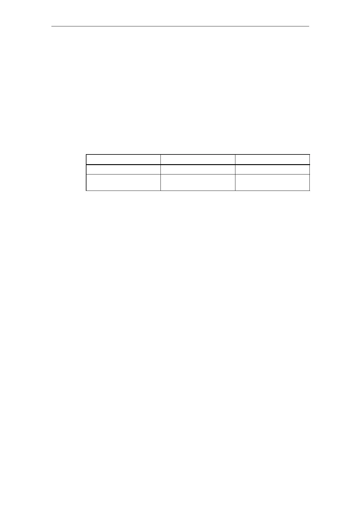
For the rotation of a coordinate system, the following G codes are used.
Table 3-2 Coordinate system rotation G codes
G code
Function Group
G68 Coordinate system rotation 16
G69 Cancel of coordinate system
rotation
16
G68 and G69 are modal G codes belonging to 16-group. When the power is turned
ON and when the NC is reset, G69 is automatically selected.
The G68 and G69 blocks must not include other G codes.
The coordinate system rotation which is called by G68 must be canceled by G69.
Command format
G68X_Y_R_;
X_, Y_ :
Absolute coordinate values of the center of rotation. If omitted, the actual position
is regarded as center of rotation.
R_ :
Rotation angle, absolute or incremental depending on G90/G91. If omitted, the va-
lue of the channel specific setting $SC_DEF AULT_ROT_FACTOR_R is used as
rotation angle.
S By specifying “G17 (or G18, G19) G68 X⋅⋅⋅Y ⋅⋅ R ⋅⋅ ; ”, the commands spe-
cified in the following blocks are rotated by the angle specified with R around
the point (X, Y). Rotation angle can be specified in units of 0.001 degree.

 Loading...


