Movement Control Commands
3.1 The coordinate system
04.07
3-46
© Siemens AG 2007 All rights reserved
SINUMERIK 802D sl/840D/840D sl/840Di/840Di sl/810D ISO Milling (PGM) -- 04.07 Edition
Examples
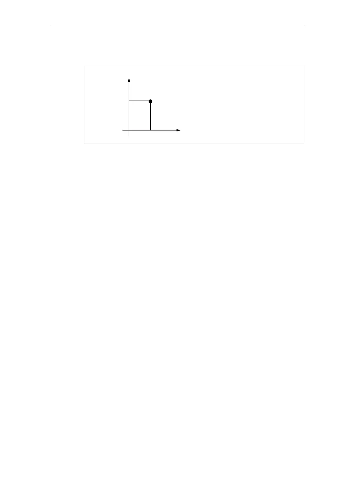
X
35.0
Y
60.0
Workpiece coordinate system 2 (G55)
Positioning to (X=35.0, Y=60.0)
in workpiece coordinate system G55.
G90 G55 G00 X35.0 Y60.0 ;
Fig. 3-5 Workpiece coordinate system G55
3.1.5 Instantaneous mapping of the ISO functions onto Siemens fra -
mes
(until powerline 7.04.2, solution line 1.4)
By changing an external workpiece zero point offset value or workpiece zero point
offset value, the workpiece coordinate systems determined through G54 to G59 as
well as G54 P{1 ... 93} are changed.
In order to change an external workpiece zero point offset value or workpiece zero
point offset value, two methods are available.
1. Entering data using the HMI panel
2. By program command G10 or G92

 Loading...


