Movement Control Commands
3.1 The coordinate system
04.07
3-54
© Siemens AG 2007 All rights reserved
SINUMERIK 802D sl/840D/840D sl/840Di/840Di sl/810D ISO Milling (PGM) -- 04.07 Edition
3.1.8 Plane selection (G17, G18, G19)
The plane where circular interpolation, tool radius offset, and coordinate system
rotation are executed is selected by specifying the following G code.
Table 3-1 Plane selection G codes
G code
Function Group
G17 XY plane 02
G18 ZX plane 02
G19 YZ plane 02
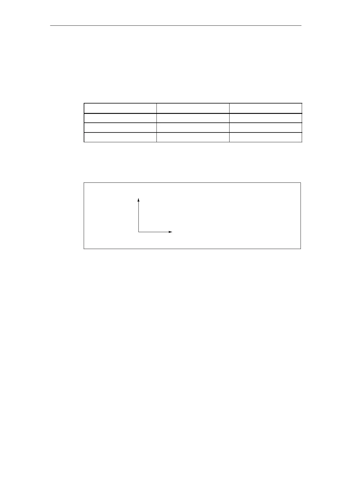
A plane is defined in the following manner (in the case of XY plane):
The horizontal axis in the first quadrant is “+X-axis” and the vertical axis in the
same quadrant “+Y-axis”.
+Y-axis
0
+X-axis
Fig. 3-10 Plane selection
S When the power is turned ON, the XY plane (G17) is selected.
S Axis move command of a single axis can be specified independent of the selec-
tion of plane by G17, G18, and G19. For example, the Z-axis can be moved by
specifying “G17 Z ....;”.
S Execution of a canned cycle is possible only in the G17 plane (hole machining
axis: Z-axis).
S The plane on which the tool radius offset is executed by the G41 or G42 com-
mand is determined by the designation of G17, G18 or G19; the plane that inc-
ludes the rotary 4th- or 5th- axis cannot be selected as the offset plane.
3.1.9 Parallel axes (G17, G18, G19)
Using the function G17 (G18, G19) <axis name>, an axis parallel to one of the
three basic axes of the coordinate system can be activated.
The three basic axes are, for example, X, Y, and Z.

 Loading...


