Movement Control Commands
3.2 Determining the coordinate value input modes
04.07
3-60
© Siemens AG 2007 All rights reserved
SINUMERIK 802D sl/840D/840D sl/840Di/840Di sl/810D ISO Milling (PGM) -- 04.07 Edition
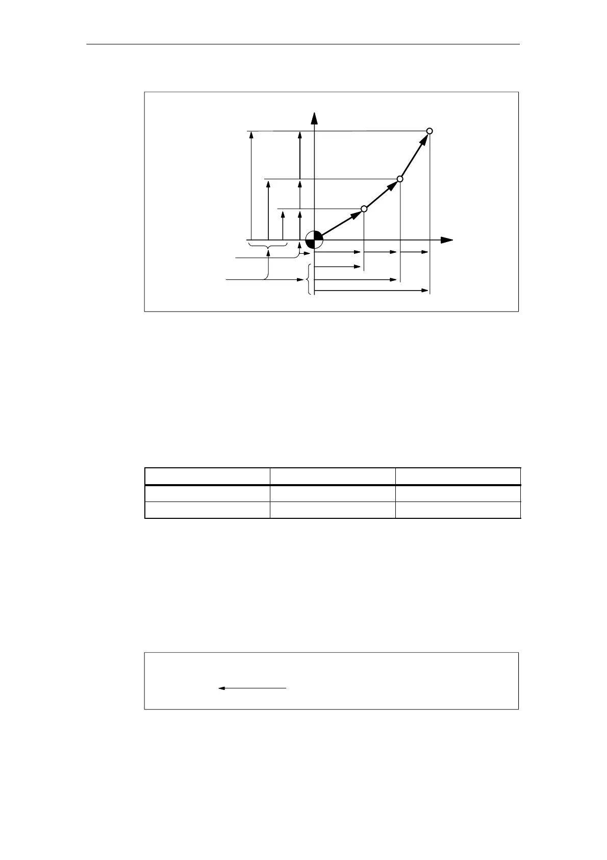
+Y-axis
Y
3
Y
2
Y
1
Y
6
Y
5
Y
4
X
4
X
5
X
6
X
1
X
2
X
3
+X-axis
G91;
Incremental
G90;
Absolute
Fig. 3-12 Absolute/incremental commands (G90, G91)
3.2.2 Inch/Metric input designation (G20, G21)
It is possible to select the dimension unit for the input data between “mm” and
“inch”. For this selection, the following G codes are used.
Table 3-4 Dimension unit selection G codes
G code
Function Group
G20 Input in “inch” system 06
G21 Input in “mm” system 06
Command format
G20 and G21 should be specified at the beginning of a program in a block without
other commands. When the G code which selects the input dimension unit is
executed, the following values are processed in the selected dimension unit: sub-
sequent programs, offset amount, a part of parameters, a part of manual operation
and display.
G291;
G20;
·
·
·
Designating the input in “inch” system
Fig. 3-13 Example pf programming

 Loading...


