Movement Control Commands
3.1 The coordinate system
04.07
3-53
© Siemens AG 2007 All rights reserved
SINUMERIK 802D sl/840D/840D sl/840Di/840Di sl/810D ISO Milling (PGM) -- 04.07 Edition
For easier programming, a kind of sub--workpiece coordinate system can be set
whenever a program is created in a workpiece coordinate system. Such a sub--
coordinate system is called a local coordinate system.
Format
G52 X... Y... Z... ; Local coordinate system set
G52 X0 Y0 Z0 ; Local coordinate system cancel
X, Y, Z: Local coordinate system origin
Explanations
A local coordinate system can be set in all the workpiece coordinate systems (G54
to G59) by specifying G52 X... Y... Z...;. Within the workpiece coordinate system,
the origin of each local coordinate system is set to the position determined by X, Y,
and Z.
Whenever a local coordinate system is set, the motion commands subsequently
commanded in the absolute mode (G90) correspond to the coordinate values wit-
hin the local coordinate system. By determining the G52 command through the
zero point of a new local coordinate system in the workpiece coordinate system,
the local coordinate system can be changed.
Match the zero point of the local coordinate system with that of the workpiece coor-
dinate system in order to cancel the local coordinat e system and to determine the
coordinate value within the workpiece coordinate syst em.
The position value displayed as the coordinate value of workpiece coordinate sy-
tem refers to the zero point of workpiece coordinate system even if the local coor-
dinate system is set by specifying G52.
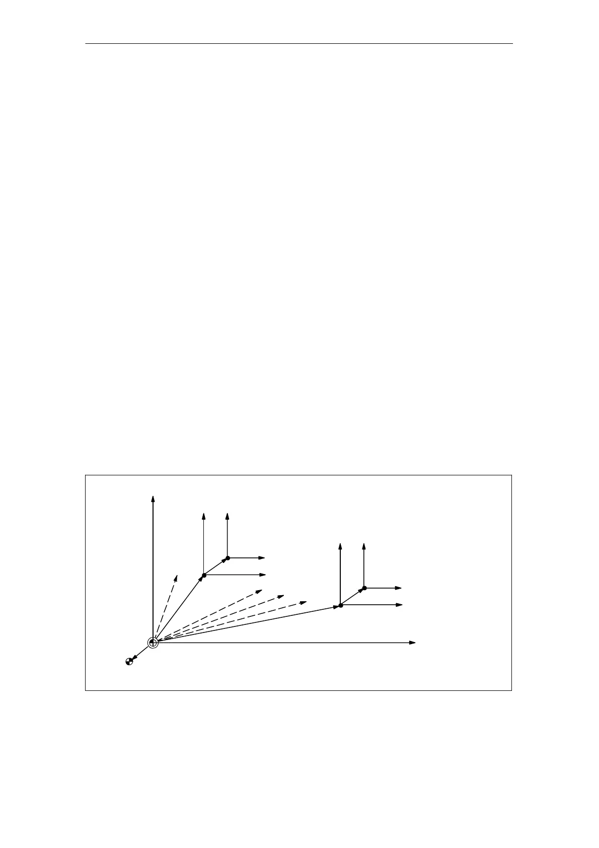
Machine coordinate system origin
Reference point
(Local coordinate system)
(G55 : Workpiece coordinate system 2)
(Local coordinate system)
(G59 : Workpiece coordinate system 6)
G54
G56
G57
G58
(Machine coordinate system)
Fig. 3-9 Setting the local coordinate system

 Loading...


