Movement Control Commands
3.1 The coordinate system
04.07
3-57
© Siemens AG 2007 All rights reserved
SINUMERIK 802D sl/840D/840D sl/840Di/840Di sl/810D ISO Milling (PGM) -- 04.07 Edition
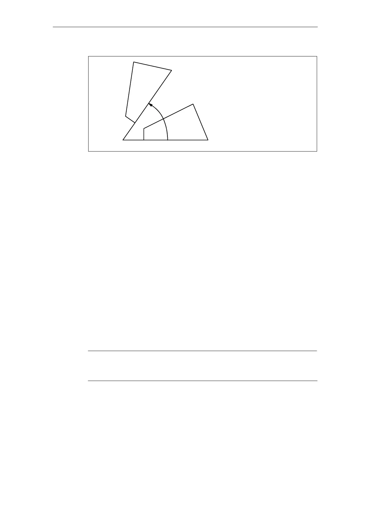
R
(X, Y)
X, Y: Center of rotation
R : Angle of rotation
(CCW rotation is “+”; to be
specified in an absolute value)
Fig. 3-11 Rotation of coordinate system
S By specifying “G69;”, the coordinate system rotation mode is canceled.
S The G68 command is executed in the plane that has been selected when the
G68 command is specified. The 4th and 5th axis must be linear axes.
G17 : XY plane or Xα,Xβ plane
G18 : ZX plane or Zα,Zβ plane
G19 YZ plane or Yα,Yβ plane
Supplements to the coordinate system rotation commands
S MD $MC_MM_NUM_BASE_FRAMES must be set to a value >= 3 if coordinate
system rotation is used.
S If “X” and “Y” are omitted, the present position when the G68 block is executed
is taken as the center of rotation.
S When the coordinate system is rotated, position data are given in the rotated
coordinate system.
S Usually, the coordinate system rotation is turned ON before the start of
approach motion and turned OFF after the completion of machining.
The workpiece cannot be machined correctly if it is turned ON during
machining.
Note
For incoupling the frames between the Siemens and the ISO modes (solution line)
see section 3.1.6.

 Loading...


