Movement Control Commands
3.2 Determining the coordinate value input modes
04.07
3-63
© Siemens AG 2007 All rights reserved
SINUMERIK 802D sl/840D/840D sl/840Di/840Di sl/810D ISO Milling (PGM) -- 04.07 Edition
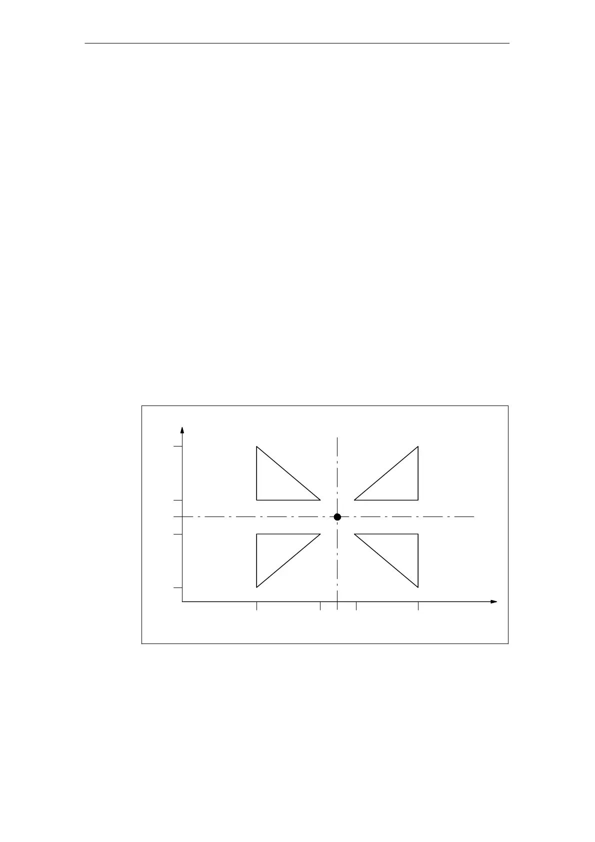
Example
_N_0512_MPF; (part program)
N01 G291;
N10 G17 G90 G00 X0 Y0; Approach start position
N30 G90 G01 G94 F6000;
N32 M98 P0513; 1) Contour as programmed in subprogram
N34 G51 X0. Y0. I-1000 J1000; 2) Mirror contour around X
N36 M98 P0513;
N38 G51 X0. Y0. I-1000 J-1000; 3) Mirror contour around X and Y
N40 M98 P0513;
N42 G51 X0. Y0. I1000 J-1000; 4) Mirror contour around Y
N44 M98 P0513;
N46 G50; Deselect scaling and mirroring
N50 G00 X0 Y0
N60 M30
_N_0513_MPF; (subprogram for 00512)
N01 G291
N10 G90 X10. Y10.;
N20 X50;
N30 Y50;
N40 X10. Y10.;
N50 M99;
Start point
-- 5 0 -- 1 0 0 1 0 5 0
-- 5 0
-- 1 0
0
10
50
2) 1)
3) 4)
Fig. 3-14 Scaling of each axis, programmable mirror image

 Loading...


