Movement Control Commands
3.2 Determining the coordinate value input modes
04.07
3-65
© Siemens AG 2007 All rights reserved
SINUMERIK 802D sl/840D/840D sl/840Di/840Di sl/810D ISO Milling (PGM) -- 04.07 Edition
Format
G51.1 X... Y... Z... ; Creating a programmable image
... ;
... ; These blocks describe the contour through which a mirror image
... ; is created with respect to the axis of symmetry
... ; specified by G51.1 X... Y... Z... ;
... ;
G50.1 X... Y... Z... ; Programmable mirror image cancel
X, Y, Z :
Position and axis of symmetry for creating a mirror image when specified through
G51.1.
Explanations
Related machine data
G51.1 uses the channel specific basic frame[1]. Therefore, set MD
$MC_MM_NUM_BASE_FRAMES > = 2.
Mirror image with respect to single axis in a specified plane
The following commands are subject to be changed when applying mirror image to
one of the axes on a preset plane as described below:
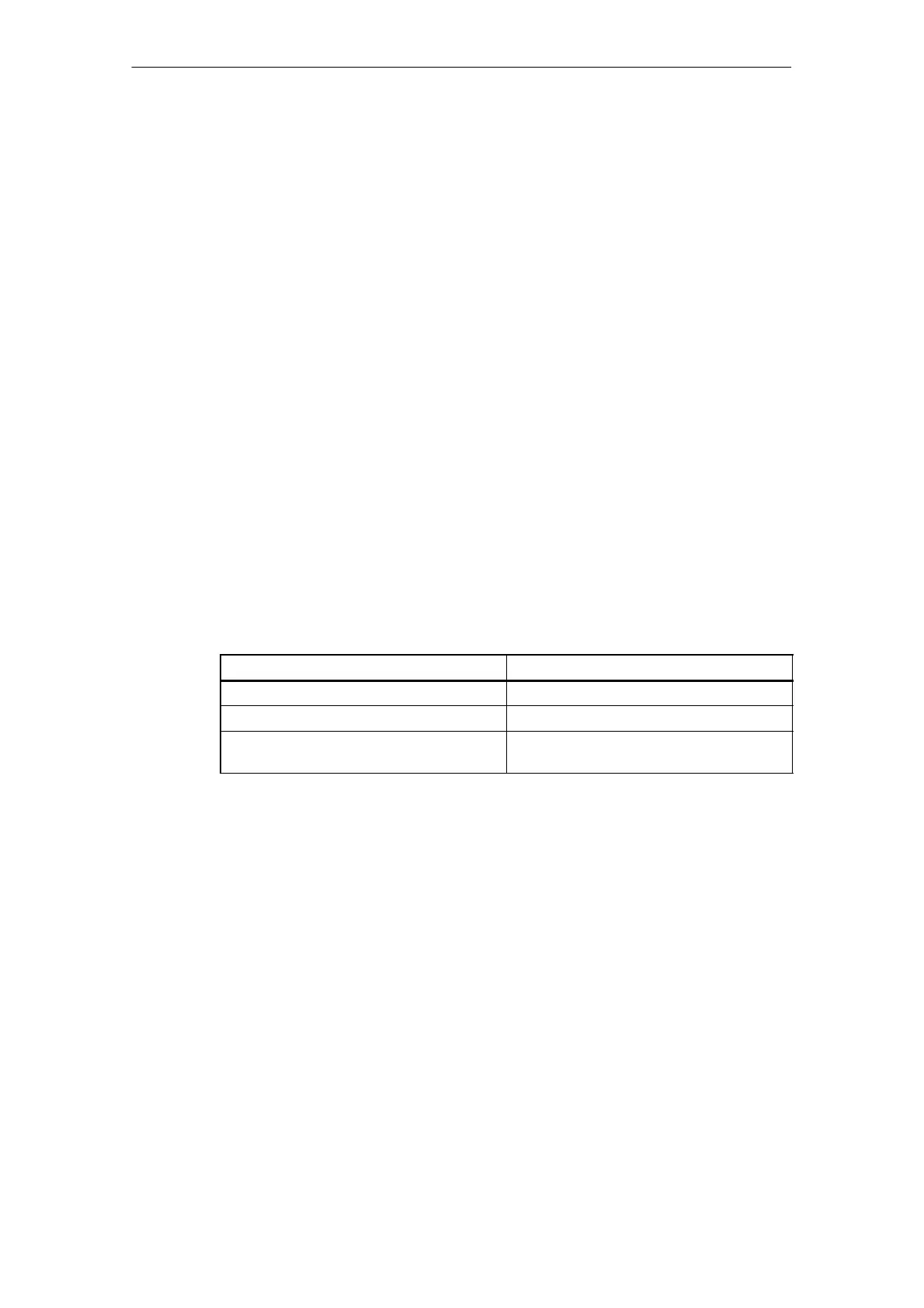
Table 3-6
Command
Explanation
Circular interpolation G02 and G03 are interchanged
Cutter compensation G41 and G42 are interchanged
Coordinate rotation CW and CCW (directions of rotation) are
interchanged
Limitations
Scaling/coordinate system rotation
Processing proceeds from program mirror image to scaling and coordinate rotation
in the stated order . The commands should be specified in this order, and, for can-
cellation, in the reverse order.
Do not specify G50.1 or G51.1 during scaling or coordinate rotation mode.
Commands related to reference position return and coordinate system
Do not use G codes related to reference position return (G27,G28,G30), or com-
mands related to the coordinate system (G52 to G59,G92, etc.) in programmable
mirror image mode.

 Loading...


