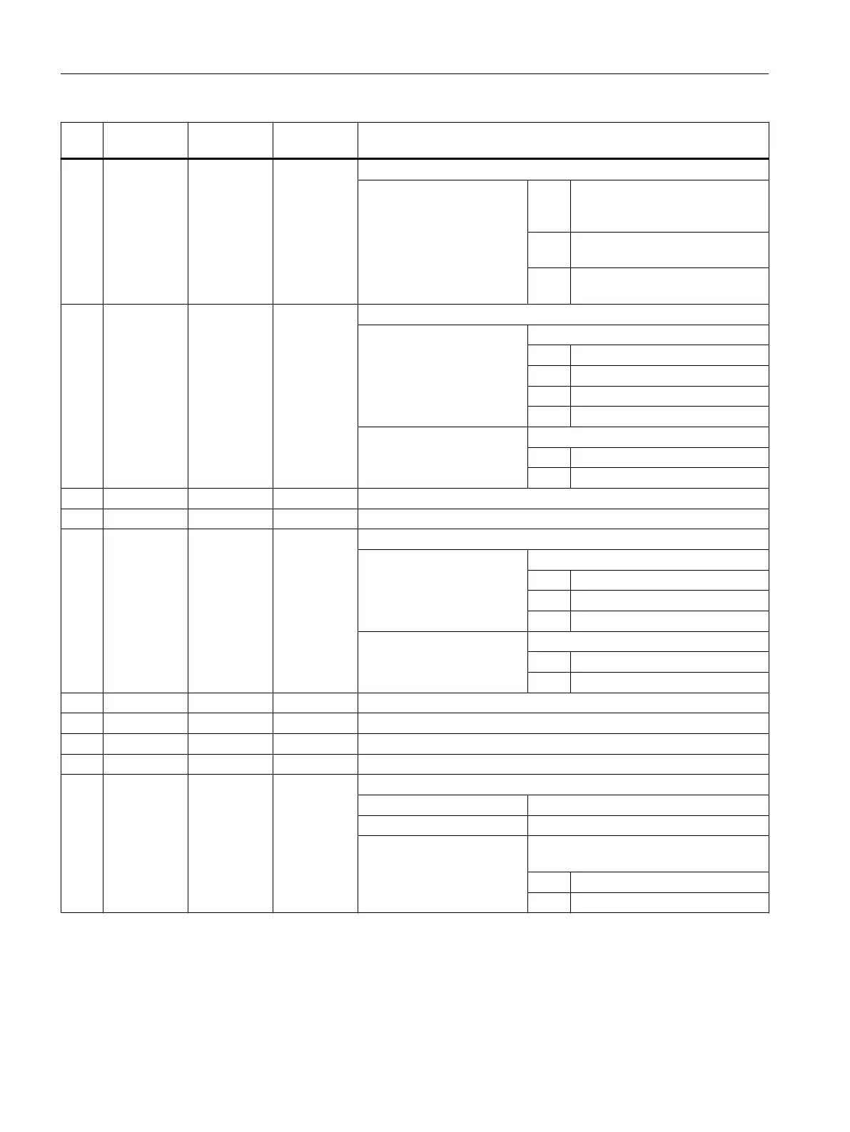
No. Parameter
mask
Parameter
internal
Data type Meaning
12 <_RL> INT Machining direction
40 = Center of contour (G40, ap‐
proach and retract: straight line
or vertical)
41 = Left of contour (G41, approach
and retract: straight line or circle)
42 = Right of contour (G42, approach
and retract: straight line or circle)
13 <_AS1> INT Contour approach movement
UNITS:
1 = Straight line
2 = Quadrant
3 = Semi-circle
4 = Approach and retraction vertically
TENS:
0 = Last movement, in the plane
1 = Last movement, spatial
14 L1 <_LP1> REAL Approach path or approach radius (inc; enter without sign)
15 FZ <_FF3> REAL Feedrate for intermediate paths (G94/G95 as to contour)
16 <_AS2> INT Contour approach movement (not vertical approach/retract)
UNITS:
1 = Straight line
2 = Quadrant
3 = Semi-circle
TENS:
0 = Last movement, in the plane
1 = Last movement, spatial
17 L2 <_LP2> REAL Retract path or retract radius (inc, to be entered without sign)
18 <_UMODE> INT Reserved
19 FS <_FS> REAL Chamfer width (inc)
20 ZFS <_ZFS> REAL Insertion depth (tool tip) on chamfering (abs/inc), see <_AMODE>
21 <_GMODE> INT Geometrical mode (evaluation of programmed geometrical data)
UNITS: Reserved
TENS: Reserved
HUNDREDS: Select machining/only calculation of start
point
0 = Compatibility mode
1 = Normal machining
Work preparation
3.25 Programming cycles externally
NC programming
1054 Programming Manual, 12/2019, 6FC5398-2EP40-0BA0
 Loading...


