No. Parameter
mask
Parameter
internal
Data type Meaning
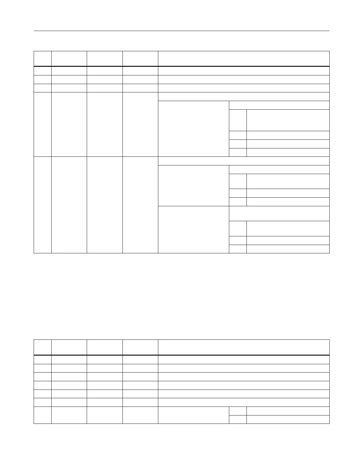
7 F <FFR> REAL Feedrate
8 FR <RFF> REAL Feedrate during retraction
9 <_GMODE> INT Reserved
10 <_DMODE> INT Display mode
UNITS: Machining plane G17/G18/G19
0 = Compatibility, the plane effective
before the cycle call remains ac‐
tive
1 = G17 (only active in the cycle)
2 = G18 (only active in the cycle)
3 = G19 (only active in the cycle)
11 <_AMODE> INT
Alternative mode (drilling)
UNITS: Drilling depth Z1 (abs/inc)
0 = Compatibility, from DP/DPR pro‐
gramming
1 = Incremental
2 = Absolute
TENS: Dwell time DT at final drilling depth in
seconds/revolutions
0 = Compatibility, from DT sign (> 0
seconds or < 0 revolutions)
1 = In seconds
2 = In revolutions
3.25.1.26 CYCLE86 - boring
Syntax
CYCLE86(<RTP>, <RFP>, <SDIS>, <DP>, <DPR>, <DTB>, <SDIR>, <RPA>,
<RPO>, <RPAP>, <POSS>, <_GMODE>, <_DMODE>, <_AMODE>)
Parameters
No. Parameter
mask
Parameter
internal
Data type Meaning
1 RP <RTP> REAL Retraction plane (abs)
2 Z0 <RFP> REAL Reference point (abs)
3 SC <SDIS> REAL Safety clearance (to be added to reference point, enter without sign)
4 Z1 <DP> REAL Drilling depth (abs), see <_AMODE>
5 Z1 <DPR> REAL Drilling depth (inc), see <_AMODE>
6 DT <DTB> REAL Dwell time at final drilling depth, see <_AMODE>
7 DIR <SDIR> INT Direction of spindle rotation 3 = M3
4 = M4
Work preparation
3.25 Programming cycles externally
NC programming
Programming Manual, 12/2019, 6FC5398-2EP40-0BA0 1075
 Loading...


