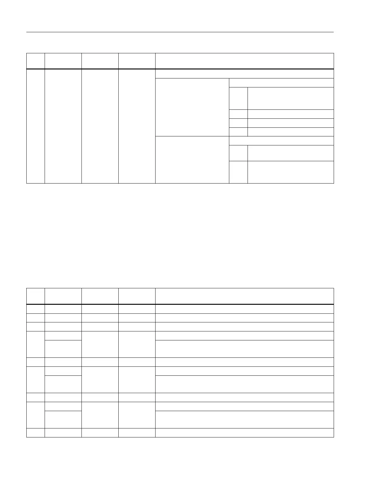
No. Parameter
mask
Parameter
internal
Data type Meaning
14 <_DMODE> INT Display mode
UNITS: Machining plane G17/G18/G19
0 = Compatibility, the plane effective
before the cycle call remains ac‐
tive
1 = G17 (only active in the cycle)
2 = G18 (only active in the cycle)
3 = G19 (only active in the cycle)
THOUSANDS:
0 = Compatibility mode: Contour
name is in NPP
1 = Contour name is programmed in
CYCLE62 and transferred to
_SC_CONT_NAME
3.25.1.29 CYCLE98 - thread chain
Syntax
CYCLE98(<_PO1>, <_DM1>, <_PO2>, <_DM2>, <_PO3>, <_DM3>, <_PO4>,
<_DM4>, <APP>, <ROP>, <TDEP>, <FAL>, <_IANG>, <NSP>, <NRC>, <NID>,
<_PP1>, <_PP2>, <_PP3>, <_VARI>, <_NUMTH>, <_VRT>, <_MID>, <_GDEP>,
<_IFLANK>, <_PITA>, <_PITM1>, <_PITM2>, <_PITM3>, <_DMODE>, <_AMODE>)
Parameters
No. Parameter
mask
Parameter
internal
Data type Meaning
1 Z0 <_PO1> REAL Reference point in Z (abs)
2 X0 <_DM1> REAL Reference point in X (abs), in diameter
3 Z1 <_PO2> REAL Intermediate point 1 in Z (abs/inc), see <_AMODE> (UNITS)
4 X1 <_DM2> REAL Intermediate point 1 in X (abs/inc), see <_AMODE> (TENS) or
X1α Thread inclination 1 (-90° to 90°)
abs is always diameter, inc is always radius
5 Z2 <_PO3> REAL Intermediate point 2 in Z, (abs/inc), see <_AMODE> (HUNDREDS)
6 X2 <_DM3> REAL Intermediate point 2 in X (abs/inc), see <_AMODE> (THOUSANDS) or
X2α Thread inclination 2 (-90° to 90°)
abs is always diameter, inc is always radius
7 Z3 <_PO4> REAL End point in Z, (abs/inc), see <_AMODE> (TEN THOUSANDS)
8 X3 <_DM4> REAL End point in X, (abs/inc), see <_AMODE> (HUNDRED THOUSANDS) or
X3α Thread inclination 3 (-90° to 90°)
abs is always diameter, inc is always radius
9 LW <APP> REAL Thread run-in (inc, to be entered without sign)
Work preparation
3.25 Programming cycles externally
NC programming
1080 Programming Manual, 12/2019, 6FC5398-2EP40-0BA0
 Loading...


