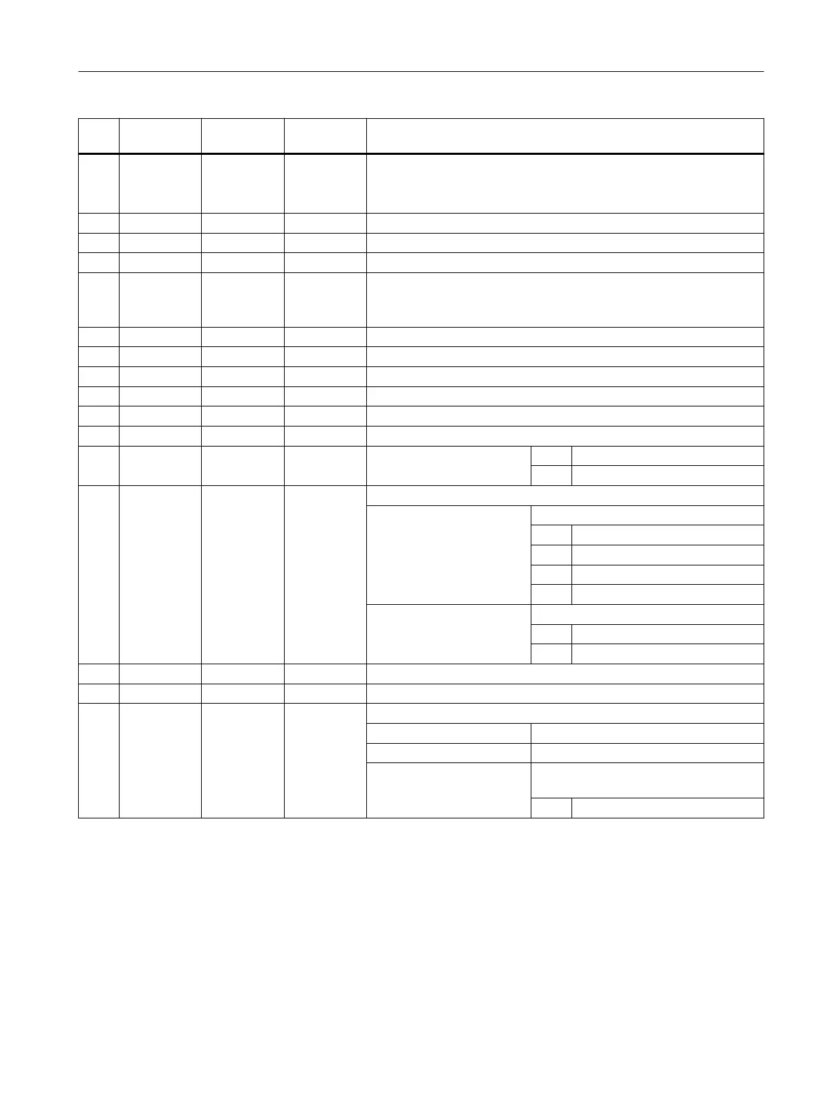
No. Parameter
mask
Parameter
internal
Data type Meaning
6
SW/L <_SWL> REAL Width across flats or edge length (depending on <_VARI>)
("SW" for width across flats, "L" for edge length)
Width across flats only if even number of edges, and single edge
7 X0 <_PA> REAL Spigot reference point, 1st axis (abs)
8 Y0 <_PO> REAL Spigot reference point, 2nd axis (abs)
9 α0 <_STA> REAL Angle of rotation, center of edge against 1st axis (X axis)
10 R1/FS1 <_RC> REAL Corner rounding with <_NUM> > 2 (radius/chamfer, see <_AMODE>)
(inc, to be entered without sign)
("R1" for radius, "FS1" for chamfer)
11 ∅ <_AP1> REAL Unmachined diameter of spigot
12 DXY <_MIDA> REAL Maximum infeed width (for unit, see <_AMODE>)
13 DZ <_MID> REAL Maximum depth infeed
14 UXY <_FAL> REAL Finishing allowance, plane
15 UZ <_FALD> REAL Finishing allowance, depth
16 F <_FFP1> REAL Machining feedrate
17 <_CDIR> INT Milling direction 0 = Down-cut
1 = Up-cut
18 <_VARI> INT Machining type
UNITS: Machining
1 = Roughing
2 = Finishing
3 = Edge finishing
5 = Chamfering
TENS: Width across flats or edge length
0 = Width across flats
1 = Edge length
19 FS <_FS> REAL Chamfer width (inc)
20 ZFS <_ZFS> REAL Insertion depth (tool tip) on chamfering (abs/inc), see <_AMODE>
21 <_GMODE> INT Geometrical mode (evaluation of programmed geometrical data)
UNITS: Reserved
TENS: Reserved
HUNDREDS: Select machining or just calculation of
start point
1 = Normal machining
Work preparation
3.25 Programming cycles externally
NC programming
Programming Manual, 12/2019, 6FC5398-2EP40-0BA0 1063
 Loading...


