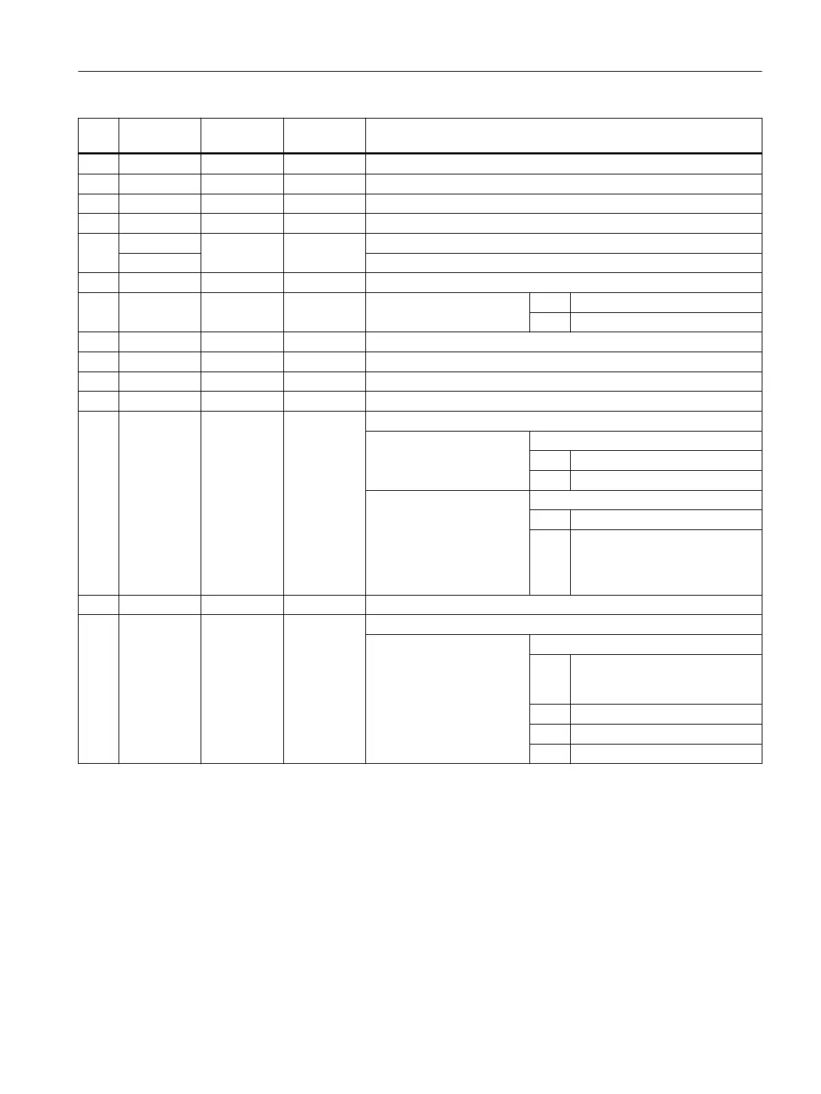
No. Parameter
mask
Parameter
internal
Data type Meaning
3 X1 <_DIAG1> REAL Depth for speed reduction, see <_AMODE> (UNITS)
4 X2 <_DIAG2> REAL Final depth, see <_AMODE> (TENS)
5 R/FS <_RC> REAL Rounding status or chamfer width, see <_AMODE> (THOUSANDS)
6 SC <_SDIS> REAL Safety clearance (to be added to reference point, enter without sign)
7 S <_SV1> REAL Constant spindle speed, see <_AMODE> (TEN THOUSANDS)
V Constant cutting rate
8 SV <_SV2> REAL Maximum speed at constant cutting speed
9 DIR <_SDAC> INT Direction of spindle rotation 3 = For M3
4 = For M4
10 F <_FF1> REAL Infeed as far as depth for speed reduction
11 FR <_FF2> REAL Reduced infeed as far as final depth
12 SR <_SS2> REAL Reduced speed as far as final depth
13 XM <_DIAGM> REAL Depth to withdraw parts gripper (abs, always diameter)
14 <_VARI> INT Machining type
UNITS: Retraction
0 = Retraction to <_SPD> + <_SDIS>
1 = No retraction at the end
TENS: Parts gripper
0 = No, do not execute M command
1 = Yes, call from CUST_TECH‐
CYC(101)- open drawer,
CUST_TECHCYC(102)- close
drawer
15 <_DN> INT D number for 2nd edge of tool; if not programmed ⇒ D+1
20 <_DMODE> INT Display mode
UNITS: Machining plane G17/G18/G19
0 = Compatibility, the plane effective
before the cycle call remains ac‐
tive
1 = G17 (only active in the cycle)
2 = G18 (only active in the cycle)
3 = G19 (only active in the cycle)
Work preparation
3.25 Programming cycles externally
NC programming
Programming Manual, 12/2019, 6FC5398-2EP40-0BA0 1077
 Loading...


