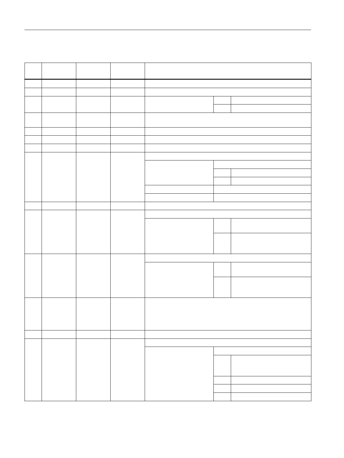
Parameters
No. Parameter
mask
Parameters
internal
Data type Meaning
1 X0 <_SPCA> REAL Reference point for position pattern (grid/frame) along the 1st axis (abs)
2 Y0 <_SPCO> REAL Reference point for position pattern (grid/frame) along the 2nd axis (abs)
3 α0 <_STA> REAL Basic angle of rotation
(angle to 1st axis)
< 0 = Clockwise rotation
> 0 = Counterclockwise rotation
4 L1 <_DIS1> REAL Distance between columns (position distance from the 1st axis, enter
without sign)
5 L2 <_DIS2> REAL Distance between rows (distance from the 2nd axis, enter without sign)
6 N1 <_NUM1> INT Number of columns
7 N2 <_NUM2> INT Number of rows
8 <_VARI> INT Machining type
UNITS: Position pattern
0 = Grid
1 = Frame
TENS: Reserved
HUNDREDS: Reserved
9 <_UMODE> INT Reserved
10 αX <_ANG1> REAL Shear angle to 1st axis (lines inclined in relation to the 1st axis)
< 0 = Clockwise measurement
(0 to -90 degrees)
> 0 = Counter-clockwise measure‐
ment
(0 to 90 degrees)
11 αY <_ANG2> REAL Shear angle to 2nd axis (columns inclined in relation to the 2nd axis)
< 0 = Clockwise measurement
(0 to -90 degrees)
> 0 = Counter-clockwise measure‐
ment
(0 to 90 degrees)
12 <_HIDE> STRING
[200]
Hidden positions
● Max. 198 characters
● Specification of consecutive position numbers, e.g. "1,3" (positions
1 and 3 are not executed)
13 <_NSP> INT Reserved
14 <_DMODE> INT Display mode
UNITS: Machining plane G17/G18/G19
0 = Compatibility, the plane effective
before the cycle call remains ac‐
tive
1 = G17 (only active in the cycle)
2 = G18 (only active in the cycle)
3 = G19 (only active in the cycle)
Work preparation
3.25 Programming cycles externally
NC programming
1098 Programming Manual, 12/2019, 6FC5398-2EP40-0BA0
 Loading...


