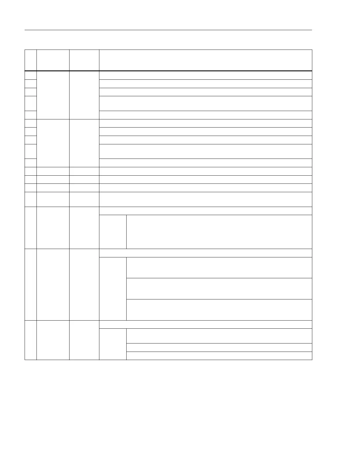
No
.
Screen
form param‐
eters
Cycle pa‐
rameters
Meaning
5 Alpha 1 S_SETV1 Starting angle for measuring at an angle for the 1st rotary axis
6 S_START_RA1: Starting angle of the 1st rotary axis
7 S_END_RA1: Final angle of 1st rotary axis
8 S_CMEA_RA1: Number of measurements of the 1st rotary axis, 3 for measuring and cal‐
culating kinematics. Up to 12 measurements are possible for interpolation points.
9 S_POS_RA2: Position of the 2nd rotary axis while measuring the 1st rotary axis
4)
10 Alpha 2 S_SETV2 Starting angle for measuring at an angle for the 2nd rotary axis
4)
11 S_START_RA2: Starting angle of the 2nd rotary axis
4)
12 S_END_RA2: Final angle of 2nd rotary axis
4)
13 S_CMEA_RA2: Number of measurements of the 2nd rotary axis, 3 for measuring and calcu‐
lating kinematics. Up to 12 measurements are possible for interpolation points.
4)
14 S_POS_RA1: Position of the 1st rotary axis while measuring the 2nd rotary axis
15 Delta S_SETV4 Tolerance value of offset vectors
16 DFA S_FA Measurement path
17 TSA S_TSA Safe area
18 Number S_NMSP Number of measurements at the same location
5)
(default=1)
19 _DMODE Display mode
Values: UNITS: Machining plane G17/G18/G19
0 = compatibility, the plane active before the cycle call remains active
1 = G17 (only active in the cycle)
2 = G18 (only active in the cycle)
3 = G19 (only active in the cycle)
20 _AMODE Alternative mode
Values: ONES: Tolerance check yes/no
0 = no
1 = yes: Evaluation of the tolerance values of the vectors -> S_SETV4, S_SETV5
TENS: Automatic calibration
0 = without automatic calibration
1 = automatic calibration
HUNDREDS: Automatic starting angle
0 = set starting angle is used
1 = automatic calculation of the starting angle, for each measuring point
21 S_KNUM Number of the WO to be corrected for reference head measurement
Values UNITS: The correction is always applied to the coarse offset, the fine offset is
deleted
TENS: 1 ... 99 number of the adjustable WO (1=G54)
THOUSANDS: 9 correction active, adjustable WO
1)
All default values = 0 or marked as default = xx
2)
Spindle is tracked in the switching direction of the probe if SD54760 bit 17 = 1
3)
There is an operator prompt with M0 before entering. The vectors cannot be entered until the NC has been started. If the
measuring program is interrupted with RESET, no calculated vectors are entered. Vectors are entered only if the tolerance
of the offset vectors is not exceeded in the calculation.
4)
Rotary axis 2 only for kinematics with 2 rotary axes
5)
Display depends on the general SD54760 $SNS_MEA_FUNCTION_MASK_PIECE.
Work preparation
3.25 Programming cycles externally
NC programming
1188 Programming Manual, 12/2019, 6FC5398-2EP40-0BA0
 Loading...


