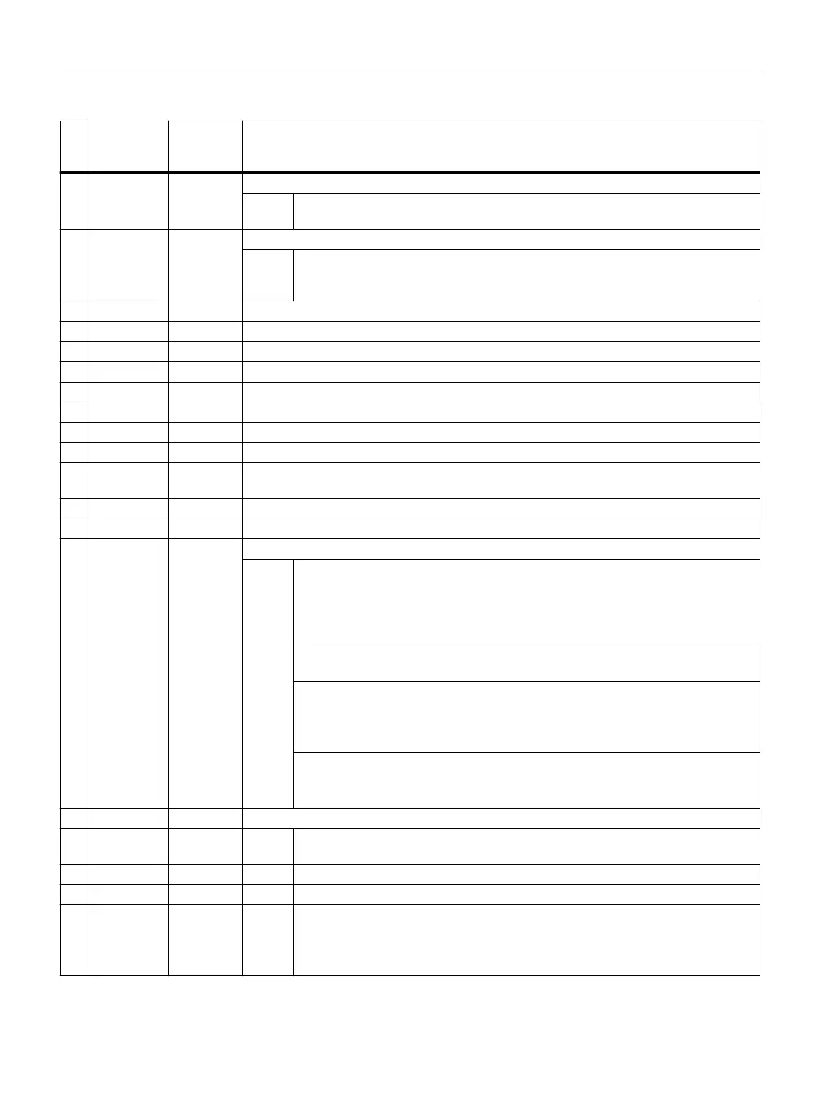
No. Screen
form param‐
eter
Cycle pa‐
rameter
Meaning
4 X0 S_MA Measuring axis
Val‐
ues:
1 = 1st axis of the plane (for G18 Z)
2 = 2nd axis of the plane (for G18 X)
5 +- S_MD Measuring direction
Val‐
ues:
0 = No selection (measuring direction is determined from actual value)
1 = Positive
2 = Negative
6 Z2 S_ID Offset
7 DFA S_FA Measurement path
8 TSA S_TSA Safe area
9 VMS S_VMS Variable measuring velocity for calibration
2)
10 alpha1 S_STA1 Starting angle when measuring milling tools
11 alpha2 S_CORA Offset angle when measuring milling tools with reversal
8)
12 TZL S_TZL Work offset when measuring milling tools. When calibrating S_TZL = 0
13 DIF S_TDIF Dimensional difference check
14 Measure‐
ments
S_NMSP Number of measurements at the same location
2)
(default=1)
15 EVN S_EVNUM Number of the empirical mean value memory
2), 9)
16 S_MCBIT Reserved
17 _DMODE Display mode
Val‐
ues:
UNITS: Machining plane G17/G18/G19
0 = Compatibility, the plane active before the cycle call remains active
1 = G17 (only active in the cycle)
2 = G18 (only active in the cycle)
3 = G19 (only active in the cycle)
TENS: Cutting edge position for turning and milling tools
(only for display in the input screens 1 to 9)
HUNDREDS: Tool type
0 = Turning tool
1 = Milling tool
2 = Drill
THOUSANDS: The approach strategy with reference to the tool probe
0 = PLUS [X/Z]; X if tool position axial, Z if tool position radial
1 = MINUS [X/Z]; X if tool position axial, Z if tool position radial
18 _AMODE Alternative mode
Val‐
ues:
UNITS: Reserved
TENS: Reserved
HUNDREDS: Reserved
THOUSANDS: approach starting position after measurement for calibration and
single measurement (see S_MVAR - UNITS)
0 = Tool is located, offset by DFA with respect to the probe edge
1 = Approach starting position
1)
All default values = 0 or marked as default=x
Work preparation
3.25 Programming cycles externally
NC programming
1190 Programming Manual, 12/2019, 6FC5398-2EP40-0BA0
 Loading...


