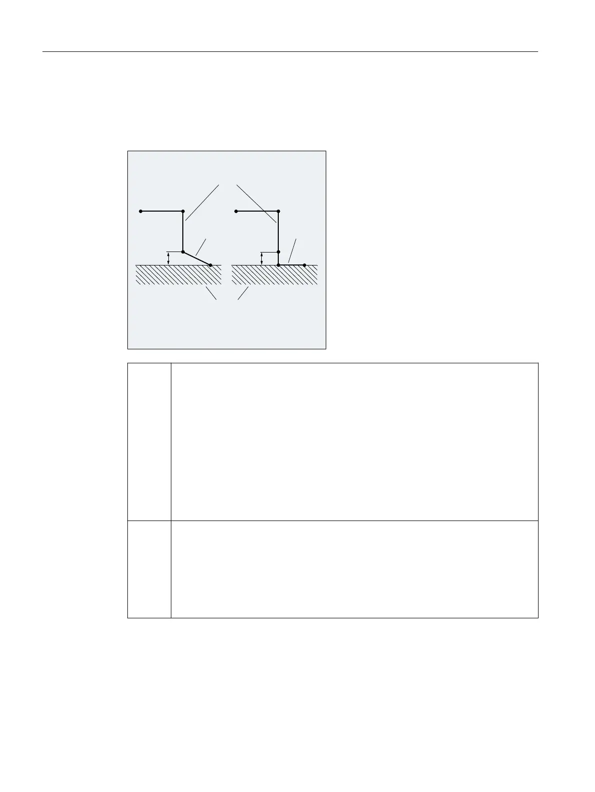
Motion steps between start point and end point (G340 and G341).
In all cases, the movements are made up of one or more straight lines and, depending on the
G command for determining the approach contour, an additional straight line or a quadrant or
semicircle. The two variants of the path segmentation are shown in the following figure:
0DFKLQLQJSODQH
,QIHHGPRYHPHQW
6WUDLJKWOLQHFLUFOH
RUKHOL[
6WUDLJKWOLQH
RUFLUFOH
$SSURDFKPRYHPHQWGHSHQGHQWRQ**
',6&/',6&/3
**
3
3
3
3
3
3
3
3
3
G340: Approach with a straight line from point P
0
to point P
1
. This straight line is parallel to the
machining plane, if parameter DISRP has not been programmed.
Infeed perpendicular to the machining plane from point P
1
to point P
3
to the safety clearance
to the machining plane defined by the DISCL parameter.
Approach end point P4 with the curve determined by the G command of the second group
(straight line, circle, helix). If G247 or G347 is active (quadrant or semicircle) and start point
P
3
is outside the machining plane defined by the end point P
4
, a helix is inserted instead of
a circle. Point P
2
is not defined or coincides with P
3
.
The circle plane or the helix axis is determined by the plane, which is active in the SAR block
(G17/G18/G19), i.e. the projection of the start tangent is used by the following block, instead
of the tangent itself, to define the circle.
The movement from point P
0
to point P
3
takes place along two straight lines at the velocity
valid before the SAR block.
G341: Approach with a straight line from point P
0
to point P
1
. This straight line is parallel to the
machining plane, if parameter DISRP has not been programmed.
Infeed perpendicular to the machining plane from point P
1
up to the safety clearance to the
machining plane defined by the DISCL parameter in point P
2
.
Infeed perpendicular to the machining plane from point P
2
to point P
3
. Approach end point
with the curve determined by the G command of the second group. P
3
and P
4
are located
within the machining plane, with the result that a circle is always inserted instead of a helix
with G247 or G347.
In all cases that include the position of the active plane G17/G18/G19 (circular plane, helical
axis, infeed motion perpendicular to the active plane), any active rotating frame is taken into
account.
Fundamentals
2.10 Tool radius compensation
NC programming
276 Programming Manual, 12/2019, 6FC5398-2EP40-0BA0
 Loading...


