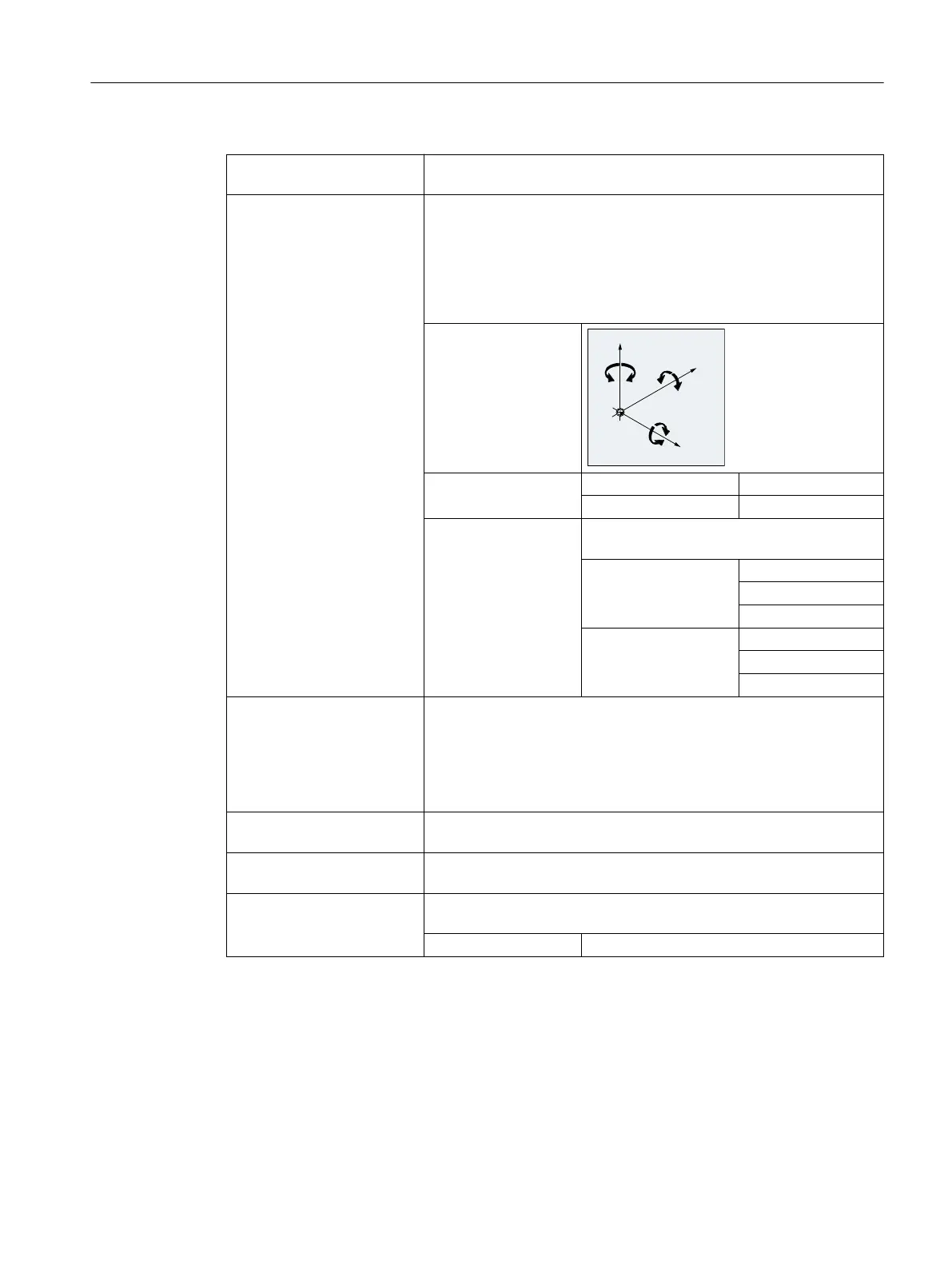
TRANS/ATRANS: Workpiece coordinate system offset in the direction of the specified ge‐
ometry axis or axes
ROT/AROT: Workpiece coordinate system rotation:
● By linking individual rotations around the specified geometry axis or
axes
or
● Around the angle RPL=... in the current working plane
(G17/G18/G19)
Direction of rotation:
Rotation sequence: With RPY notation: Z, Y', X''
With Euler angle: Z, X', Z''
Range of values: The angles of rotation are only defined unam‐
biguously in the following ranges:
With RPY notation: -180 ≤ x ≤ 180
-90 < y < 90
-180 ≤ z ≤ 180
With Euler angle: 0 ≤ x < 180
-180 ≤ y ≤ 180
-180 ≤ z ≤ 180
ROTS/AROTS: Workpiece coordinate system rotation by means of the specification of
solid angles
The orientation of a plane in space is defined unambiguously by speci‐
fying two solid angles. Therefore, up to two solid angles may be pro‐
grammed:
ROTS/AROTS X... Y... / Z... X... / Y... Z...
CROTS: CROTS works in the same way as ROTS but refers to the valid frame in
the database.
SCALE/ASCALE: Scaling in the direction of the specified geometry axis or axes to in‐
crease/reduce the size of a contour
MIRROR/AMIRROR:
Workpiece coordinate system mirroring by means of mirroring (direction
change) the specified geometry axis
Value: Freely selectable (in this case: "0")
Supplementary conditions
● Frame statements must be programmed in a separate NC block.
● Frame statements can be used individually or combined as required.
Fundamentals
2.12 Coordinate transformations (frames)
NC programming
Programming Manual, 12/2019, 6FC5398-2EP40-0BA0 309
 Loading...


