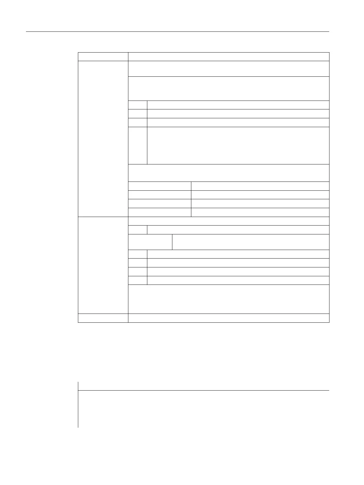
<Axis>: Name of channel axis used for measurement
<Mode>: Two-digit (xx) number indicating the operating mode (measuring mode and meas‐
uring system)
Units decade: Measuring mode
Specifies whether the trigger events are to be activated in chronological or pro‐
grammed order.
x0 Cancel measuring job.
x1 Up to 4 different trigger events can be activated simultaneously.
x2 Up to 4 trigger events that can be activated successively.
x3 Up to 4 different trigger events can be activated in succession, but there is
no monitoring of trigger event 1 at the start (alarms 21700/21703 are sup‐
pressed).
Note:
MEAC does not support this mode.
Tens decade: Measuring system
Specifies the measuring system with which measuring is to be performed.
0x (or no specification) Active measuring system
1x Measuring system 1
2x Measuring system 2
3x Both measuring systems
<TE>: Trigger event to initiate measurement
Type: INT
Range of val‐
ues:
-2, -1, 1, 2
(+)1 Positive edge of probe 1
-1 Negative edge of probe 1
(+)2 Positive edge of probe 2
-2 Negative edge of probe 2
Note:
If the measuring process is performed with two measuring systems, a maximum of
two trigger events can be programmed (positive or negative edge). The measured
values of both measuring systems are acquired for both the trigger events.
<MeasMem>: Number of FIFO (circular buffer)
Examples
Example 1: Axis-specific measurement with delete distance-to-go in mode 1 (evaluation in
chronological sequence)
a) Measuring with one measuring system
Program code Comment
...
N100 MEASA[X]=(1,1,-1) G01 X100 F100 ; Measuring in mode 1 with active measur-
ing system. Wait for measuring signal
with positive/negative edge from probe 1
for travel path to X=100.
Work preparation
3.7 Special motion commands
NC programming
616 Programming Manual, 12/2019, 6FC5398-2EP40-0BA0
 Loading...


