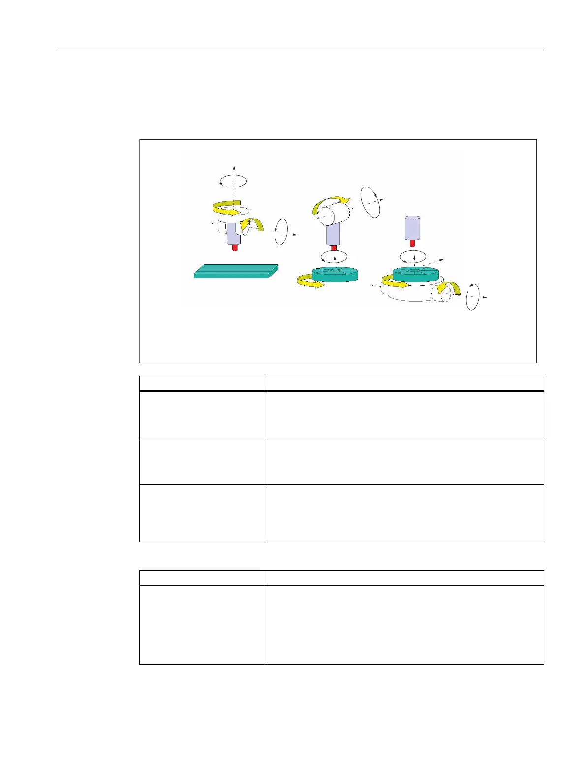
Machine kinematics for three, four and five axis transformation (TRAORI)
Either the tool or the tool table can be rotatable with up to two rotary axes. A combination of
swivel head and rotary table (single-axis in each case) is also possible.
Rotated workpiece
Machine type 2 with
axis sequence AC
Rotated tool Rotated
workpiece
Machine type 3 with
axis sequence BC
Rotated tool
Machine type 1 with
axis sequence CA
A
CC
B
A
C
Y
X
Tool table, fixed
Tool table, can
be rotated
about Z axis
Tool table, can
be rotated
about X axis
and Z axis
Swivel head,
fixed
Swivel head,
can be rotated
about Y axis
Swivel head,
can be rotated
about X axis
and Z axis
Z Z
Y
X
Z
Machine type Programming of orientation
Three-axis transformation ma‐
chine types 1 and 2
Programming of tool orientation only in the plane, which is perpendic‐
ular to the rotary axis. There are
two translatory axes (linear axes) and
one axis of rotation (rotary axis).
Four-axis transformation ma‐
chine types 1 and 2
Programming of tool orientation only in the plane, which is perpendic‐
ular to the rotary axis. There are
three translatory axes (linear axes) and
one axis of rotation (rotary axis).
Five-axis transformation ma‐
chine types 3
Single-axis swivel head and
single-axis rotary table
Programming of orientation transformation. Kinematics with
three linear axes and two orthogonal rotary axes.
The rotary axes are parallel to two of the three linear axes. The first
rotary axis is moved by two Cartesian linear axes. It rotates the third
linear axis with the tool. The second rotary axis rotates the workpiece.
Generic 5/6-axis transformations
Machine type Programming of orientation transformation
Generic five/six-axis transfor‐
mation machine types 4
Two-axis swivel head with tool
which rotates around itself and
single-axis rotary table
Programming of orientation transformation. Kinematics with
three linear axes and three orthogonal rotary axes.
The rotary axes are parallel to two of the three linear axes. The first
rotary axis is moved by two Cartesian linear axes. It rotates the third
linear axis with the tool. The second rotary axis rotates the workpiece.
The basic tool orientation can also be programmed with additional ro‐
tation of the tool around itself with the THETA rotary angle.
When calling "generic three-, four-, and five/six-axis transformation", the basic orientation of the
tool can also be transferred. The restrictions in respect of the directions of the rotary axes no
longer apply. If the rotary axes are not exactly vertical to one another or existing rotary axes are
Work preparation
3.9 Transformations
NC programming
Programming Manual, 12/2019, 6FC5398-2EP40-0BA0 657
 Loading...


