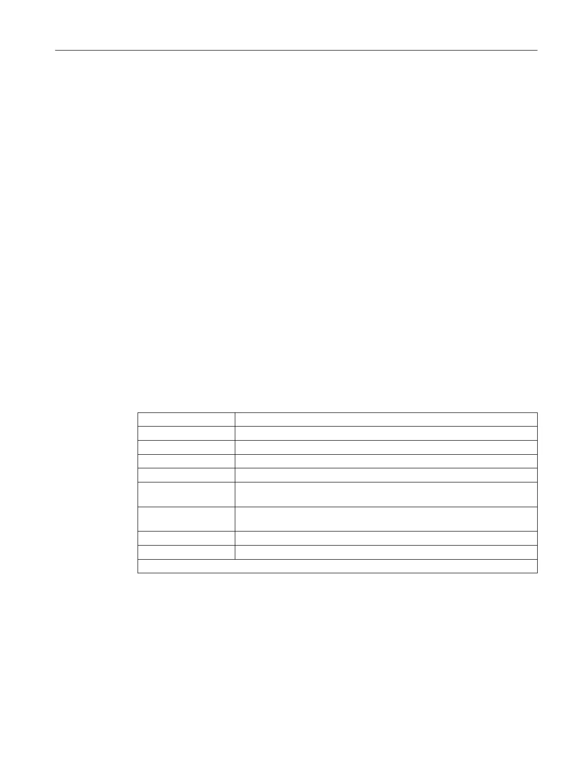
Syntax
Rotary axis positions
G1 X<Value> Y<Value> Z<Value> A<Value> B<Value> C<Value>
Euler angles
G1 X<Value> Y<Value> Z<Value> A2<Value> B2<Value> C2<Value>
Direction vector
G1 X<Value> Y<Value> Z<Value> A3<Value> B3<Value> C3<Value>
Surface normal vector at block start
G1 X<Value> Y<Value> Z<Value> A4<Value> B4<Value> C4<Value>
Surface normal vector at the end of the block
G1 X<Value> Y<Value> Z<Value> A5<Value> B5<Value> C5<Value>
Lead angle
LEAD=<Value>
Tilt angle
TILT=<Value>
Meaning
G1: Linear interpolation
X, Y, Z: Linear axis positions
A, B, C: Rotary axis positions
A2=, B2=, C2=: Angle programming (Euler or RPY angle)
A3=, B3=, C3=: Directional vectors in the X, Y and Z coordinates of the WCS.
A4=, B4=, C4=: Surface normal vectors at the start of the block in the X, Y and Z coordinates
of the WCS.
A5=, B5=, C5=: Surface normal vectors at the end of the block in the X, Y and Z coordinates
of the WCS.
LEAD= : Leading angle
1)
TILT= : Tilt angle
1)
1) The interpretation of the angle indications depend on the setting in MD21094 $MC_ORIPATH_MODE
Further information
5-axis programs are usually generated by CAD/CAM systems and not entered at the control.
So the following explanations are directed mainly at programmers of postprocessors.
Work preparation
3.9 Transformations
NC programming
Programming Manual, 12/2019, 6FC5398-2EP40-0BA0 669
 Loading...


