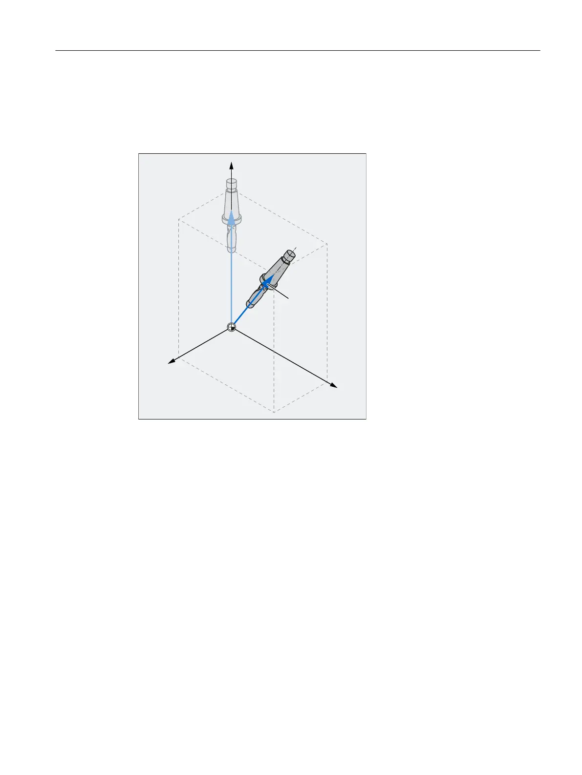
Programming the directional vector
The components of the direction vector are programmed with A3, B3, C3. The vector points
towards the tool adapter; the length of the vector is of no significance.
Vector components that have not been programmed are set equal to zero.
%
$
;
<
&
=
2
X, Y, Z Coordinate axes of the WCS
A3, B3,
C3
Components of the directional vector
O Orientation vector
Figure 3-3 Programming the directional vector
Programming the tool orientation with LEAD and TILT
The resultant tool orientation is determined from:
● Path tangent
● Surface normal vector
At the start of the block A4, B4, C4 and at the end of the block A5, B5, C5
● Lead angle LEAD
Angle in the plane defined by the path tangent and surface normal vector
● Tilt angle TILT at end of block
Angle in the plane, perpendicular to the path tangent relative to the surface normal vector
Work preparation
3.9 Transformations
NC programming
Programming Manual, 12/2019, 6FC5398-2EP40-0BA0 671
 Loading...


