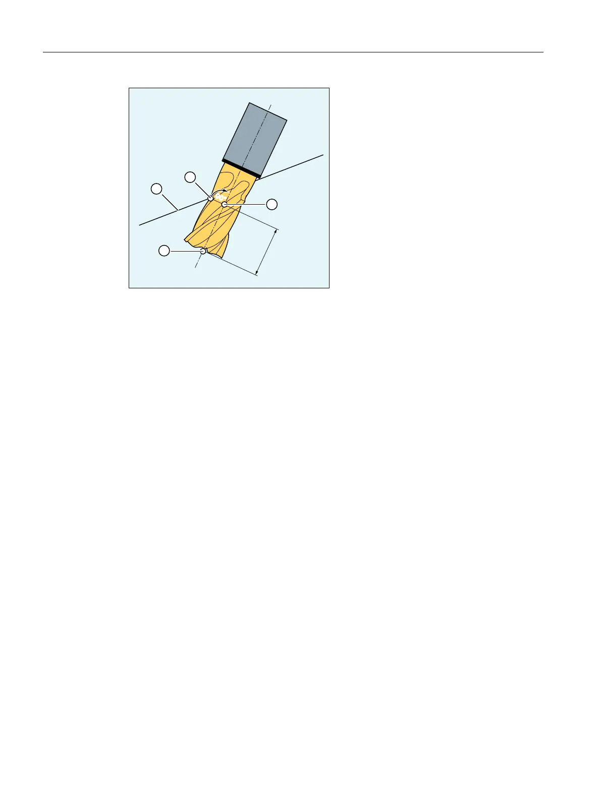
① Programmed path
② Milling tool machining point
③ Milling tool reference point
④ Milling tool tip
ISD Insertion depth (InSertion Depth)
Figure 3-9 Insertion depth
Tool radius compensation referred to a differential tool
3D TRC for circumferential milling referred to a differential tool is activated via the CUT3DCD
command. It should be applied if the programmed contour refers to the center-point path of a
standard tool, and a tool other than a differential tool is used for machining. When calculating
the 3D tool radius compensation, only the wear value of the radius of the active tool
($TC_DP15) and any programmed tool offsets OFFN and TOFFR/TOFFLR are taken into
account. The basic radius ($TC_DP6) of the active tool is not taken into account.
Pocket milling with inclined side walls for circumferential milling with CUT3DC
In this 3D tool radius compensation, a deviation of the mill radius is compensated by infeed
toward the surface normals to be machined. The plane, in which the milling tool face is located,
remains unchanged if the insertion depth ISD has remained the same. For example, a milling
tool with a smaller radius than a standard tool would not reach the pocket base, which is also
the limitation surface. For automatic tool infeed, this limitation surface must be known to the
control, see Section "3D circumferential milling taking into account a limitation surface
(CUT3DCC, CUT3DCCD) (Page 765)".
Work preparation
3.13 Tool offsets
NC programming
758 Programming Manual, 12/2019, 6FC5398-2EP40-0BA0
 Loading...


