Programming and Operating Manual (Turning)
112 01/2017
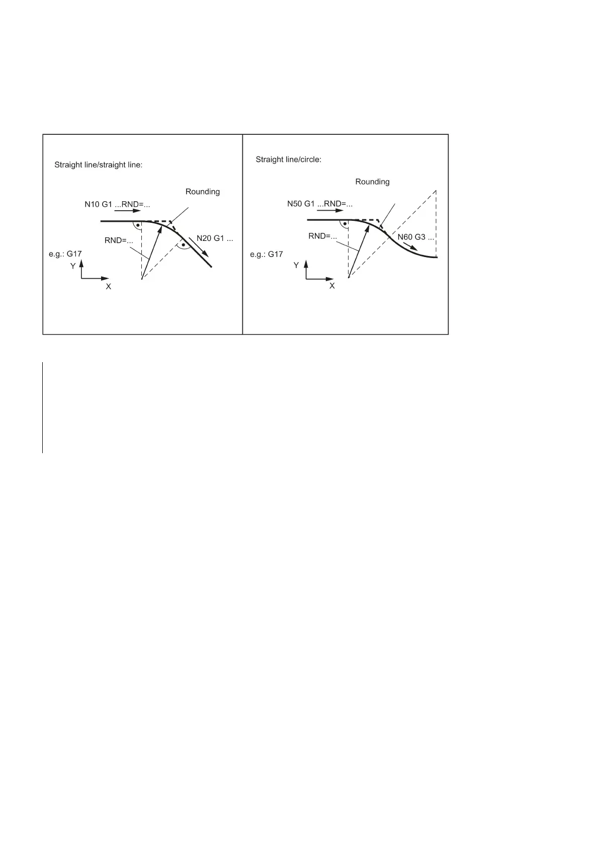
A circle contour element can be inserted with tangential connection between the
linear and circle contours
in any
combination.
See the following illustration for examples for inserting roundings:
Programming examples for rounding
N10 G0 X100 Z100 G94 F100
; Insert 1 rounding with radius 8 mm, feedrate F
N50 G1 X40 FRCM= 200 RNDM=7.3
; Modal rounding, radius 7.3 mm with special feedrate FRCM
(modal)
; continue inserting this rounding - to N70
Contour definition programming
Functionality
If direct end point values for the contour are not visible in a machining drawing, angle values can also be used for straight
line determination. In a contour corner, you can insert the elements chamfer or rounding. The corresponding instruction
CHR= ... or RND=... is written in the block that leads to the corner.
Contour definition programming can be used in blocks with
.
Theoretically, any number of straight-line blocks can be combined and a rounding or chamfer inserted in between. Every
straight line must be clearly identified by point values and/or angle values.
; Specification of angle to define a straight line
; Insert rounding, value: Radius of chamfer
; Insert chamfer, value: Side length of the chamfer
If radius and chamfer are programmed in one block, only the radius is inserted regardless of the programming sequence.
An angle can be entered to uniquely define the straight line path if only one end point coordinate of the plane is known for a
straight line or for contours across multiple blocks the cumulative end point. The angle is always referred to the Z axis
(normal case: G18 active). Positive angles are aligned counter-clockwise.