Programming and Operating Manual (Turning)
150 01/2017
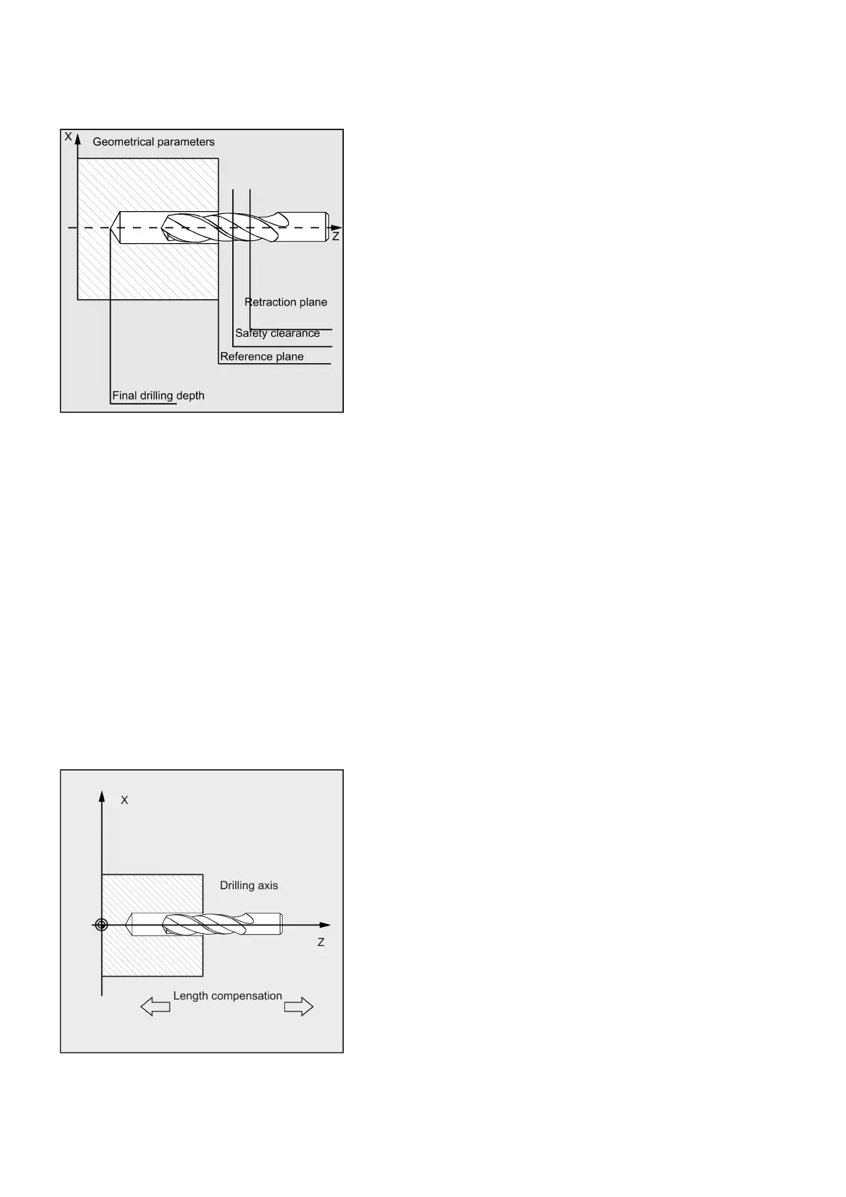
See the following illustration for geometrical parameters:
Requirements
Call and return conditions
Drilling cycles are programmed independently of the actual axis names. The drilling position must be approached in the
higher-level program before the cycle is called.
The required values for feedrate, spindle speed and direction of spindle rotation must be programmed in the part program if
there are no defining parameters in the drilling cycle.
The G functions and the current data record active before the cycle was called remain active beyond the cycle.
In the case of drilling cycles, it is generally assumed that the current workpiece coordinate system in which the machining
operation is to be performed is to be defined by selecting plane G17 and activating a programmable offset. The drilling axis
is always the axis of this coordinate system which stands vertically to the current plane.
A tool length compensation must be selected before the cycle is called. Its effect is always perpendicular to the selected
plane and remains active even after the end of the cycle.
In turning, the drilling axis is thus the Z axis. Drilling is performed to the end face of the workpiece.
See the following illustration for drilling axis when turning: