Programming and Operating Manual (Turning)
26 01/2017
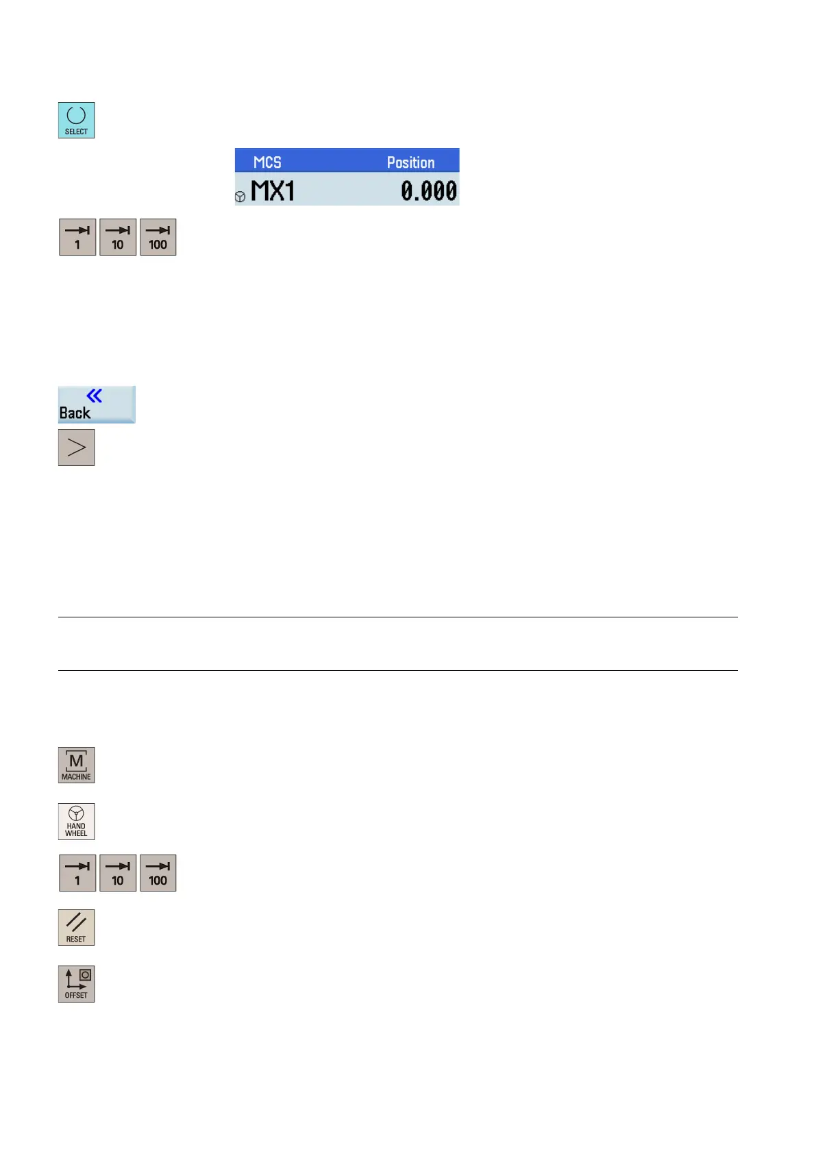
Press the desired vertical softkey (<X> ... <MZ1>) or this key for the handwheel ass
ign
ment.
The handwheel symbol which appears to the left of the selected axis (for example, the X
axis) indicates that you have assigned the handwheel to the selected axis.
eys on the MCP to select the required override increment.
1: The override increment is 0.0005 mm (X)/0.001 mm (Z).
10: The override increment is 0.005 mm (X)/0.010 mm (Z).
100: The override increment is 0.050 mm (X)/0.100 mm (Z).
witched to REL or WCS, the override increment of the X axis equals
Rotate the handwheel to make the selected axis approach the workpiece.
Machine a surface to verify the handwheel assignment.
Press this softkey to close the window for handwheel assignment.
Press this key to return to the main screen of the machin
ing operating area.
Measuring the tool manually
Precondition
You must first create a tool (Page 20) and activate it (Page 23) before measuring the tool. Make sure all the axes have been
referenced (Page 18).
Measuring the tool manually (without the Y axis)
Note
This section takes the turning tool measurement for example. If you have created other types of tools, proceed through the
steps below to finish measuring all the tools.
Operating sequence
Measuring the X axis of the tool
Select the machining operating area.
h to handwheel control mode.
Select a suitable override feedrate,
activate the spindle (Page 23) and then use the hand-
wheel to move the tool to cut the external cylindrical surface of the workpiece for about 1
mm along the X axis and 15 mm along the Z axis. Then retract the tool along the Z axis.
Press this key to reset the system. Mea
sure the diameter of the workpiece machined in the
previous step with a calliper.
Select the offset operating area.