Programming and Operating Manual (Turning)
01/2017
275
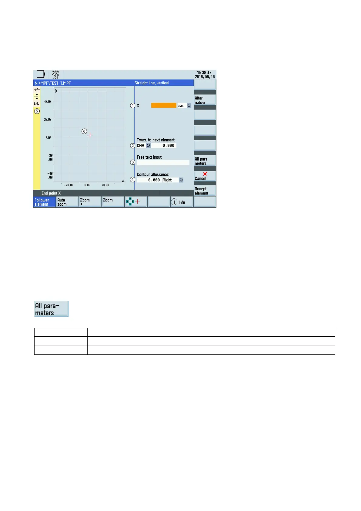
Parameters for contour elements
Parameters for programming straight lines
Absolute (abs)/incremental (inc) end position in X or Z direction
Transition element to the next contour is a chamfer (CHR) or a radius (RND). CHR=0 or RND=0 means no transition
element.
Input field for supplementary comments, such as F1000 feedrate values, H or M functions. If comments are entered as
text, they must always be started with a semicolon ";".
-based parallel contour allowance. It is displayed as an allowance in the graphics window.
The contour chain which displays the start point and programmed contour elements. The current position in the chain
is color-highlighted.
The graphics window which displays the progress of the contour as you c
onfigure the parameters for the contour ele-
The following additional parameters are displayed after you press this softkey:
Length of the straight line
Pitch angle with reference to X axis