Programming and Operating Manual (Turning)
01/2017
167
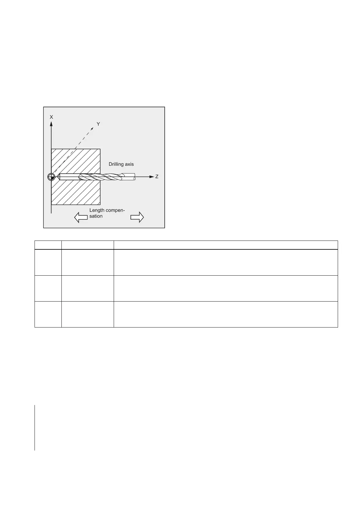
The following figure presents the options for the drilling axes to be selected.
With G18:
● AXN=1 ;Corresponds to Z
● AXN=2 ;Corresponds to X
● AXN=3 ;Corresponds to Y (if Y axis is present)
See the following illustration for drilling axis of G18:
Using AXN (number of the drilling axis) to program the drilling axis enables the drilling axis to be directly programmed.
X/Y G17 AXN=1: 1st axis of the current plane is X
AXN=2: 2nd axis of the current plane is Y
1)
AXN=3: 3rd axis of the current plane is Z
Z/X G18 AXN=1: 1st axis of the current plane is Z
AXN=2: 2nd axis of the current plane is X
AXN=3: 3rd axis of the current plane is Y
1)
Y/Z G19 AXN=1: 1st axis of the current plane is Y
1)
AXN=2: 2nd axis of the current plane is Z
AXN=3: 3rd axis of the current plane is X
For example, to machine a center hole (in Z) in the G17 plane, you program:
G17
AXN=3
Programming example: Tapping without encoder
Tapping is carried out without encoder at position X0; the drilling axis is the Z axis. The parameters SDR and SDAC for the
direction of rotation must be assigned; parameter ENC is assigned the value 1, the value for the depth is the absolute value.
Lead parameter PIT can be omitted. A compensating chuck is used in machining.
N10 G90 G0 G54 D1 T6 S500 M3
; Specification of technology values
; Approach drilling position
; Setting the path feedrate
N40 CYCLE840(3, 0, , -15, 0, 1, 4, 3, 1, , ,3)
; Cycle call; dwell time 1 s; direction
of rotation for retraction M4; direction
of rotation after cycle M3; no safety
clearance
The MPIT and PIT parameters have been