Programming and Operating Manual (Turning)
01/2017
267
Enter the following coordinates or angles in the respective input fields:
Coordinates of the given point (PP)
Slope angle of the straight line (A1)
Distance of the new point with reference to PP
Slope angle of the connecting straight line (A2) with reference to A1
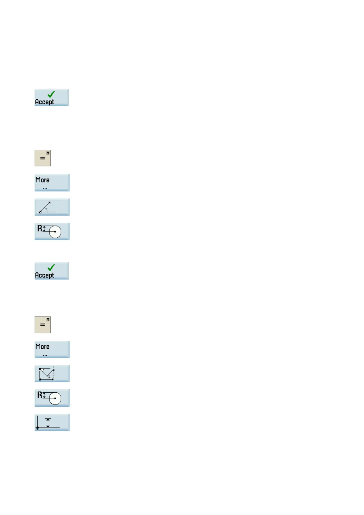
Press this softkey to calculate the abscissa and ordinate values of the point.
The abscissa is the first axis, and the ordinate is the second axis of the plane. The abscissa
value is displayed in the input field from which the calculator function
has been called, and
the value of the ordinate is displayed in the next input field. If the function is called from the
part program editor, the coordinates are saved with the axis names of the selected basic
plane.
Calculating the Cartesian coordinates
Activate the calculator when you position the c
ursor on the desired input field.
wer-level menu for contour elements selection.
.
Select the desired calculation function.
This function converts the given polar coordinates into Cartesian coordinates.
Press this softkey to switch between the diameter programming and radius programming.
Enter the reference point, the vector length and the slope angle in the respective input
fields.
Press this softkey to calculate the Ca
rtesian coordinates.
The abscissa value is displayed in the input field from which the calculator function has
been called, and the value of the ordinate is displayed in the next input field. If the function
is called from the part program editor, the coor
dinates are saved with the axis names of the
Calculating the end point
Activate the calculator when you position the cursor on the desired input field.
-level menu for contour elements selection.
Select the desired calculation function.
This function calculates the missing end point of the straight line/straight line contour section
whereby the second straight line stands vertically on the first straight line.
Press this softkey to switch between the diameter programming and radius programming.
Press this softkey to define the given end point when the ordinate value is given.