5 Operation
5.4 Configuration modes
Manual
170
SIPART DR21
C73000-B7476-C143-08
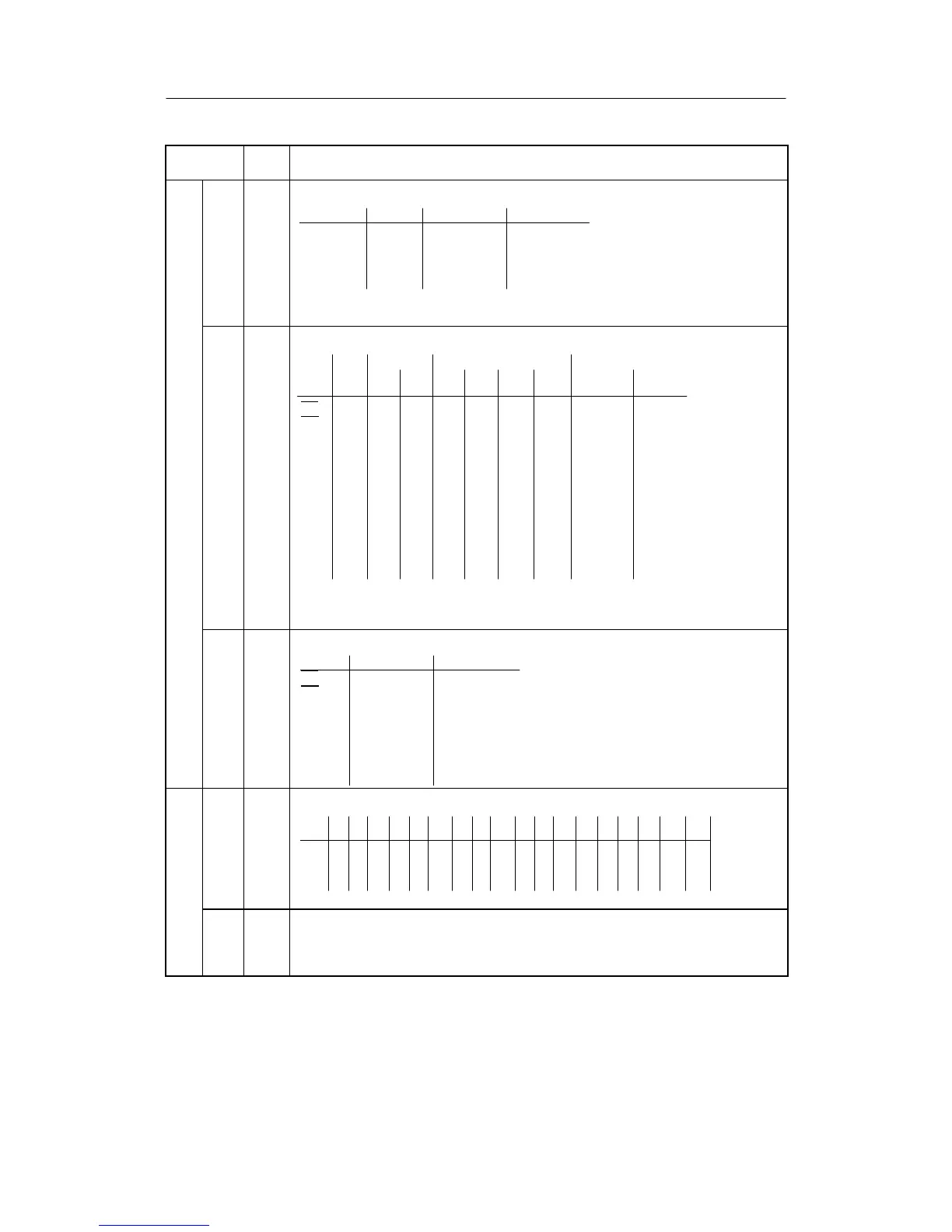
Structure
switch
switch
posi-
tion
Function
S57 Assignment +/--y
[0]
1
2
3
DO1 DO2 DO7 (relay) DO8 (relay)
-- -- + Δy--Δy
+Δy--Δy-- --
-- -- Δy+Δy--
+Δy-- -- --Δy
Note:
S57 has priority over S58 to S68
Assignment of message signals to digital outputs
Digital outputs
S58
S59
S60
S61
S62
S63
S64
S65
S66
S67
S68
Stand. contr. Slot 3 Standard controller
none DO1 DO2 DO3 DO4 DO5 DO6 DO7 DO8
(relay) (relay)
RB
[0]123456 7 8
RC
[0]123456 7 8
H [0]123456 7 8
Nw[0]123456 7 8
A1 0[1]23456 7 8
A2 01[2]3456 7 8
A3 [0]123456 7 8
A4 [0]123456 7 8
MUF[0]123456 7 8
+Δw[0]123456 7 8
--Δw[0]123456 7 8
Notes:
If DO1/2 or DO7/8 are occupied by S57 with +/--y, no double assignment is possible!
S67 and S68 only active at S1=4 (control unit/process display).
Direction of control action of the DOs on assigned message signals
S69
S70
S71
S72
S73
S74
S75
24 V = High 0 V = High
RB
[0] 1
RC
[0] 1
H[0] 1
Nw [0] 1
A1/A2 [0] 1
A3/A4 [0] 1
MUF [0] 1
Assignment of A1/A2 and A3/A4 to process variables
value alarms
S76
S77
xdx1 x wxvwvy y1y2AIAIAIAIAIAIAI AI|xd|
12341A2A3A4A
A1/[0]1234567891011121314151617*)
A2
A3/[0]1234567891011121314151617*)
A4
*) as of software version -B5

 Loading...


