7 Application examples for configuring the controller
7.3 Configuration examples
Manual
202
SIPART DR21
C73000-B7476-C143-08
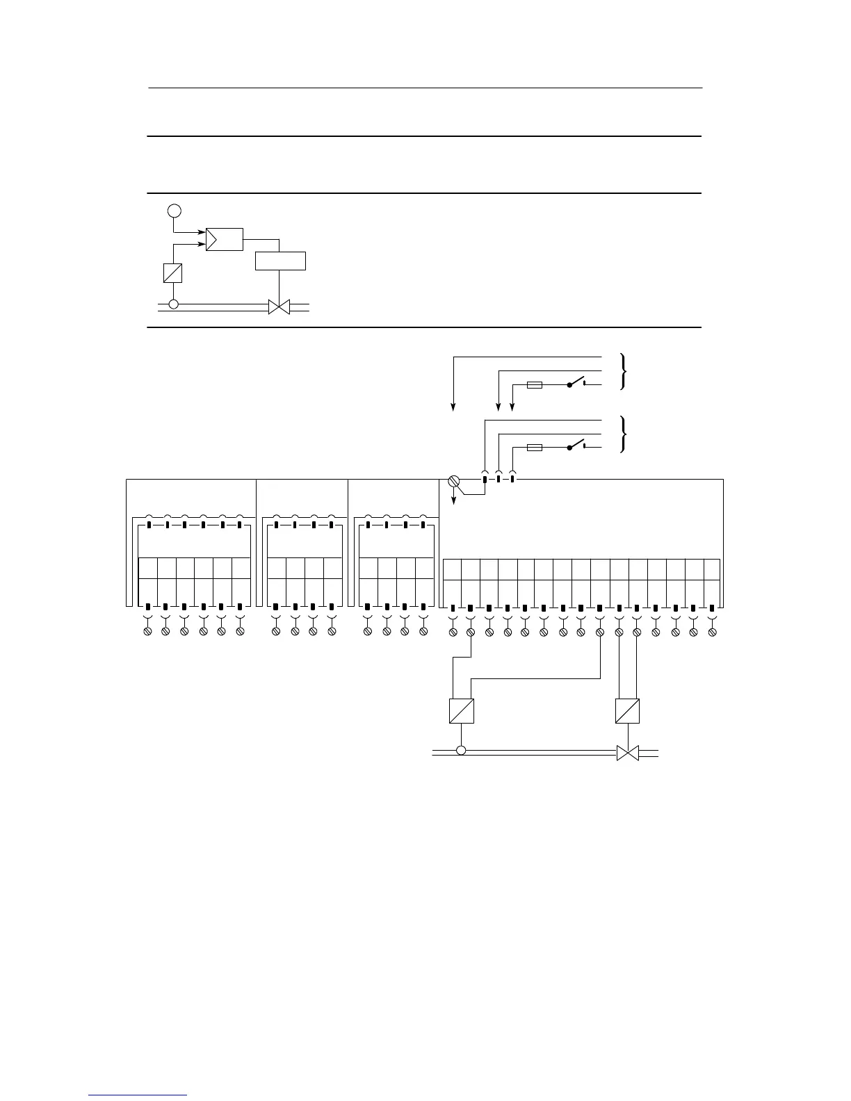
Configuration example K3 Fixed s etpoint controller as a K-controller
Controlled v ariable by a two-wire transmitter
x
w
I
y
Drive
The controlled variable x from the transmitter goes to the analog
input AI1 of the controller.
The transmitter is fed by the same lines. The input signal range
and the output manipulated variable of the controller are 4 to
20 mA.
Please read the foreword to chapter 7.1, page 193
Setting the structure switches:
S1 = 0
S2 = 0
S4 = 2, 3
S56 = 1
Slot 1
AI3
not
used
Slot 2
AI4
not
used
Slot 3
Limit value
Option module
6DR2801-8D
M1 A1 R2 M2R1 A2
123 456
When using AI1 the feed voltage at the transmitter may
be only 15 V under worst case conditions.
--
I
+
x
--
I
+
AI1
--
PE
N
L
SIP ART DR21 standard controller
PE
N
L
UC 24 C
AC 115 V
AC 230 V
6DR2100-5 (AC230 V/115 V)
6DR2100-4 (UC 24 C)
AI1
+
AI2
--
AI2
+
DI1 DI2
DO
1
DO
2
L+ AO
123 456789101112
-Δy
L
13 14 15
+Δy
GND GND