7 Application examples for configuring the controller
7.3 Configuration examples
Manual
SIPART DR21
C73000-B7476-C143-08
203
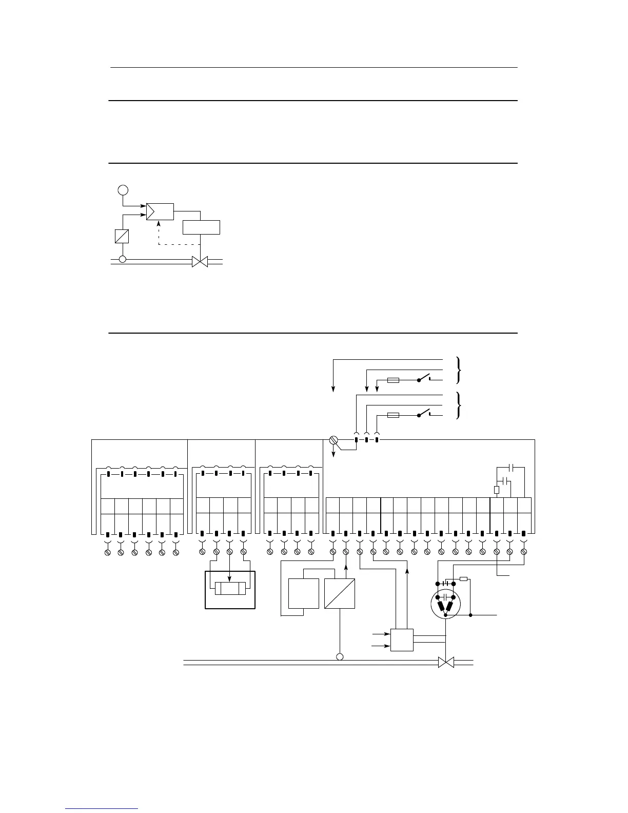
Configuration example S1 Slave control, three-position step controller with internal feedback;
Controlled v ariable by a two-wire transmitter, externally fed
position feedback via an ESR;
External setpoint potentiometer
The controlled variable of the transmitter goes to the analog input AI1, the posi-
tion feedback of ESR to the analog input AI2 of the controller . A signal range of
0 to 20 mA is programmed for both inputs.
Transmitter and ESR are externally fed.
A cascade is disconnected preferably by switching the master controller to
manual mode. The slave controller is still in automatic mode, its setpoint is still
the output signal of the master controller, i.e. now its manual manipulated varia-
ble. The slave controller therefore becomes the fixed setpoint controller.
Switching back the master controller to automatic mode and thus the intercon-
nection of the cascade takes place bumplessly but not without drift if the set-
point of the slave controller but not that of the master controller was adjusted
during switching.
The drifting after switching back can be prevented if the master controller is
programmed with structure switch S43 = 1 to x tracking. Then the setpoint of
the master controller is tracked to the actual value which changes with the
delay time of the system as long as the cascade is disconnected.
x
w
ext
y
Drive
y
R
R
A
R
E
ΔR
S
AI1
--
PE
N
L
PE
N
L
UC 24 C
AC 115 V
AC 230 V
AI1
+
AI2
--
AI2
+
DI1 DI2
DO
1
DO
2
L+ AO
123 456789101112
Setting the structure switches:
S1 = 1
S2 = 2
S17 = 4
Slot 1
AI3
Slot 2
AI4
Spark quench-
ing internal
Slot 3
Limit value
Option module
6DR2801-8D
M1 A1 R2 M2R1 A2
123 456
not
used
M/A S E
123 4
Option module
6DR2800-8R
L+Δy
13 14 15
--Δy
S19 = 2
S42 = 1
S54 = 1
Please read the foreword in chapter 7.1, page 193 and the warnings in chapter 2.1 (from page 17)
SIP ART DR21 standard controller
6DR2100-5 (AC230 V/115 V)
6DR2100-4 (UC 24 C)
External setpoint potentiometer
R=R
A
+ ΔR+R
E
WE
U
external
I
+ +--
--
x
x
ESR
U
H
+--
yR
L
R
C
N
Perform spark quen-
ching according to
EMC requirements!
+18V<U<+28V
123 4
GND GNDGND