7 Application examples for configuring the controller
7.3 Configuration examples
Manual
204
SIPART DR21
C73000-B7476-C143-08
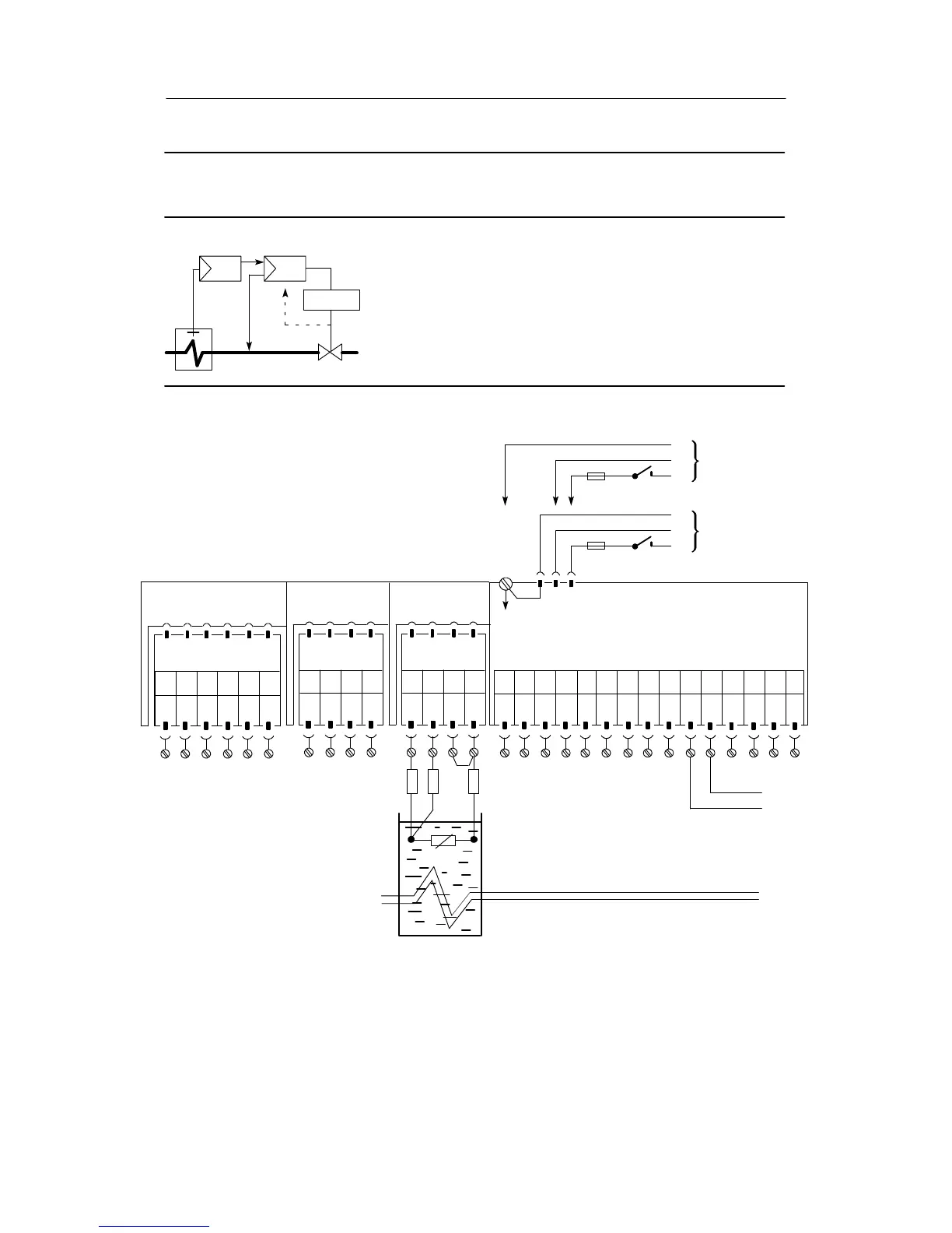
Configuration example S2 cascade control, K-controller and S-controller (internal feedback);
The controlled variables of the master controller and the slave con-
troller come directly from the resistance thermometers Pt100.
The master controller is a SIPART DR21 with K-output, the slave controller has
one three-position step output.
The controlled variables of both the master controller and slave controller come
directly from the resistance thermometers Pt100 and are connected at the ana-
log input AI3 in both controllers. The position feedback of the step switching
slave controller comes from a potentiometer , connected at the analog input AI4.
The output signal of the master controller is the setpoint for the slave controller
and is fed to its analog input AI1.
y
Drive
Command
controller K
Command
controller S
Master controller
Setting the structure switches of the master controller:
S1 = 0
S2 = 0
S6 = 4 to 7
Slot 1
AI3
Slot 2
AI4
not
used
Slot 3
Limit value
Option module
6DR2801-8D
M1 A1 R2 M2R1 A2
123 456
S8 = 4
S15 = 3
S17 = 0
Option module
6DR2800-8V
123 4
Please read the foreword in chapter 7.1, page 193 and the warnings in chapter 2.1 (from page 17)
AI1
--
PE
N
L
SIP ART DR21 standard controller
PE
N
L
UC 24 C
AC 115 V
AC 230 V
6DR2100-5 (AC230 V/115 V)
6DR2100-4 (UC 24 C)
AI1
+
AI2
--
AI2
+
DI1 DI2 DO
1
DO
2
L+ AO
123 456789101112
-Δy
L
13 14 15
+Δy
Pt100
R
L1
=R
L2
=R
L4
≤50 Ω
R
L1
R
L2
R
L4
123 4
¡
©
¢
GND GND
 Loading...


