3 Functional description of the structure switches
3.4 Controller types (S1, S42 to S45)
Manual
SIPART DR21
C73000-B7476-C143-08
65
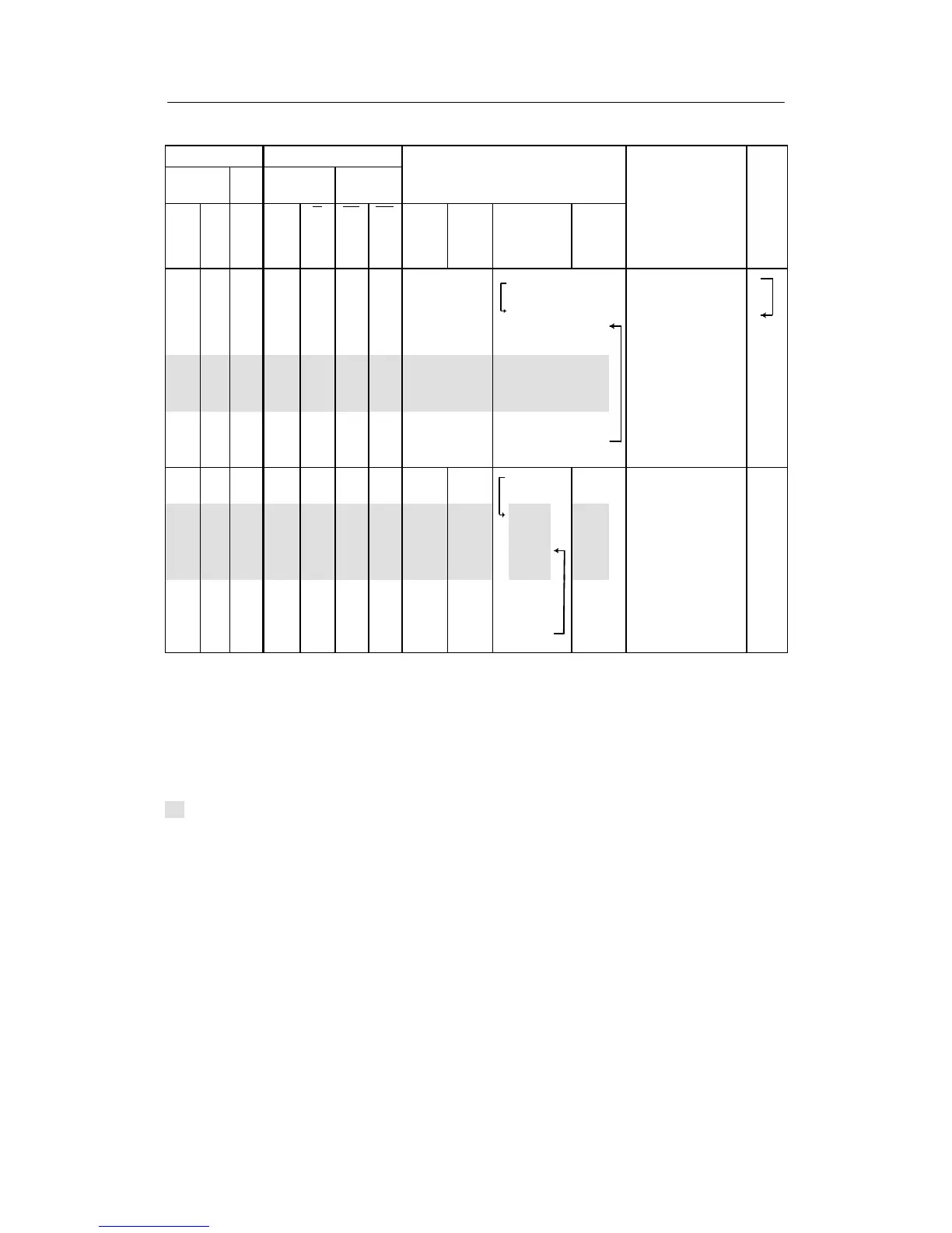
Control s igna ls Message signals
Digital
inputs
Front Front
Digital
outputs
active w at
H
∨N
∨Si
CB
1)
In-
ter-
nal
In-
ter-
nal
LED
C
LED
RB
4)
RC
4)
S43=0
S44=0
S43=1
S44=0
S43=0
S44=1
S43=1
S44=1
Explanations
ter-
fai-
lure
0 1 0 0 0 0 0 w
E
(n)
2)
w
E
(n)
2)
Automatic mode,
SPC-mode
0 0 0 0 1 0 1 wi(n,↗)
SH
3)
or
wi(n,
↗)
Automatic mode,
computer switched off,
computer in
SPC-standby
0 1 1 1 0 1 1 wi(n,↗) wi(n,↗)
Automatic mode,
computer on standby,
controller not in
SPC-standby
5)
0 0 1 1 1 1 1 wi(n,↗) wi(n,↗)
Automatic mode,
computer switched off,
computer in SPC-
standby
1 1 0 0 0 0 0
w
E
(n)
2)
x
w
E
(n)
2)
x
1 0 0 0 1 0 1
wi
(n,
↗)
x
SH
3)
or
wi
(n,
↗)
x
Manual-, tracking- or
safety mode
5)
1 1 1 1 0 1 1
wi
(n,
↗)
x
wi
(n,
↗)
x
1 0 1 1 1 1 1
wi
(n,
↗)
x
wi
(n,
↗)
x
1)
The table is shown for static CB-switching without acknowledgement (S41 = 0).
2)
Source for w
E
at S85 = 0, 1, (4, 5 as of software version -A5) is w
EA
or at S85 = 2, 3 w
ES
(SES). The external setpoint
fed in through the SES (w
ES
) is tracked. Tracking is not possible when the external setpoint is fed in via w
EA
.
3)
SH can only be reached after w
E
, if Int = 0 and CB goes from 1 → 0 (computer failure). If CB = 0 and Int is switched
from 1 → 0, wi is still active. Since SH is not tracked, switching over to SH can take place with the setpoint ramp tS.
4)
By OR-linking with the digital outputs H, N and the control signal Si no computer standby or computer operation can be
signaled in manual-, tracking- or safety operation.
5)
Factory setting
(n) tracked to the value active before switching, therefore bumpless switching
↗ adjustable
Factory setting
Table 3-4 Slave-/synchronized-/SPC-controller with Internal-/External switching S1 = 1 with tracking of
the inactive setpoint to the active S45 = 0