H
∨N
∨Si
CB
1)
Inter-
nal
In-
ter-
nal
LED
C
LED
RB
4)
RC
4)
S43=0
S44=0
S43=1
S44=0
S43=0
S44=1
S43=1
S44=1
Explanations
0 1 0 0 0 0 0 w
E
2)
w
E
2)
0 0 0 0 1 0 1 wi(↗)
SH
3)
or
wi(
↗)
Automatic mode
5)
0 1 1 1 0 1 1 wi(↗) wi(↗)
0 0 1 1 1 1 1 wi(↗) wi,↗)
1 1 0 0 0 0 0 w
E
2)
x w
E
2)
x
1 0 0 0 1 0 1 wi(↗) x
SH
3)
or
wi(
↗)
x
Manual-, tracking- or safety
mode
5)
1 1 1 1 0 1 1 wi(↗) x wi(↗) x
1 0 1 1 1 1 1 wi(↗) x wi(↗) x
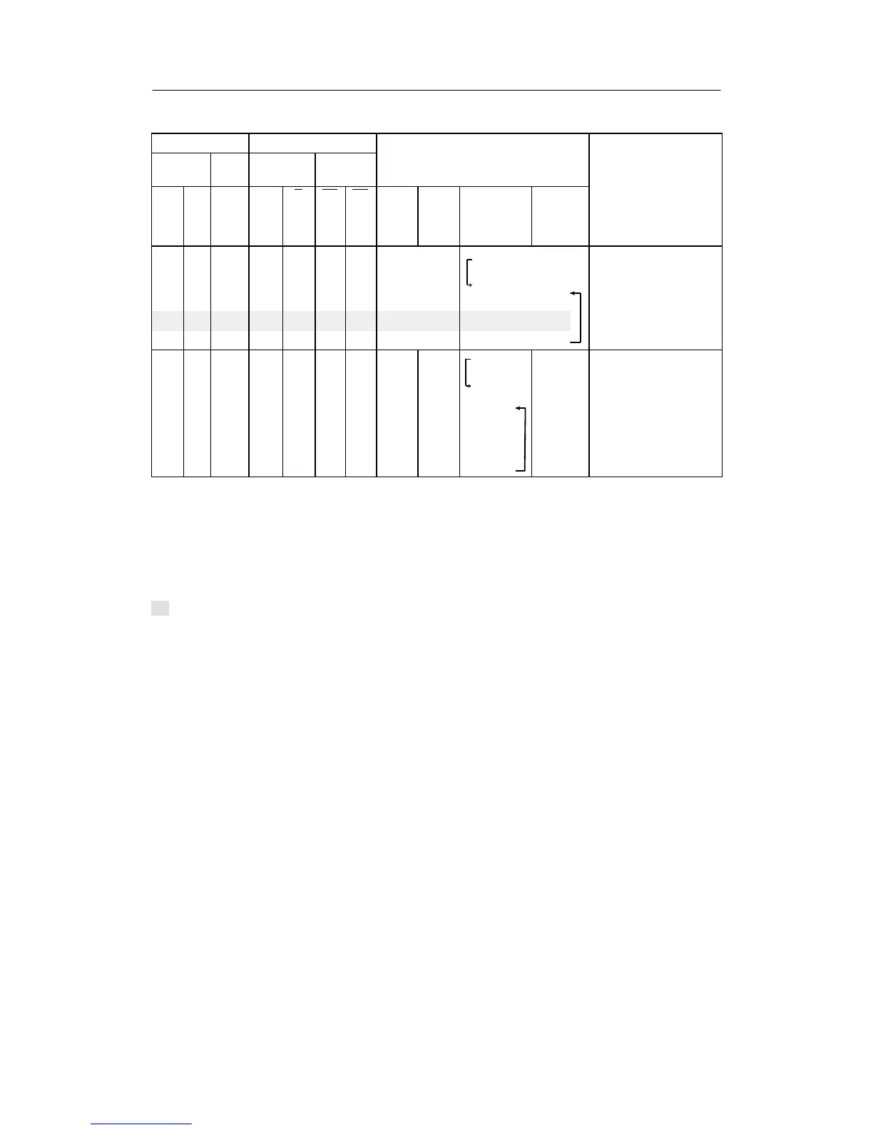
1)
The table is shown for static computer switching without acknowledgement (S41 = 0).
2)
Source for w
E
at S85 = 1, 2, (4, 5 as of software version -A5) is w
EA
or at S85 = 3, 4 w
ES
. Switching between the set-
points can take place with the setpoint ramp tS.
3)
SH can only be reached after w
E
, if Int = 0 and CB goes from 1 → 0 (computer failure). If CB = 0 and Int is switched
from 1 → 0, wi is still active. Since SH is not tracked, switching over to SH can take place with the setpoint ramp tS.
4)
By OR-linking with the digital outputs H, N and the control signal Si no computer standby or computer operation can be
signaled in manual-, tracking- or safety operation.
5)
Factory setting
↗ adjustable
Factory setting
Table 3-5 Slave-/synchronized-/SPC controller with Internal-/External switching (SPC-controller), S1 =
1 without tracking of the active setpoint to the active setpoint S45 = 1, 2 or 3 setpoint oper-
ation