3 Functional description of the structure switches
3.4 Controller types (S1, S42 to S45)
Manual
SIPART DR21
C73000-B7476-C143-08
67
Factory setting
c1=c3=0
S85
tS
w
ES
x
xd
w
E
A
0
2/3
1
1
1
0
0
CB
CB
A
Int
Int
wi
w
E
X
X
W
W
SA, SE
c1, c3
tFI
x1
x2
x3/w
EA
S43
S44
S45
Adaptation
x=x1+c1 · x2+c3
w
ES
w-c3
c4
SH
w
E
=c4·w
E
+c5
w
E
c4, c5
Factory setting
c4 = 1, c5 = 0
w
n
o
wi1
S85
wi1
ES
SES
2/3/(4/5)
1)
0/1
1)
S17,
S15,
S16,
w
0/1/(4/5)
1)
0000
I
0000
III
xx1
--
+
0000
II
0000
IV
A
=H∨N∨Si
H=Hi∨He
Note: S51 = 4 is recommended for this controller
1)
as of software version -A5
Figure
3-27,
page
104
Figure 3-1,
page 49
Figure
3-19,
page
89
tS tSH
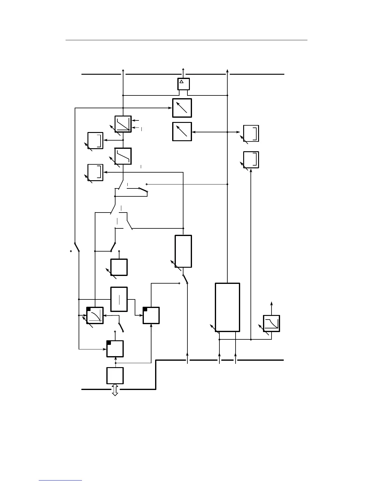
Figure 3-8 Block diagram S1 = 1 slave controller, synchronized controller, SPC-controller