3.1 Mounting and Connections
245
7UM61 Manual
C53000-G1176-C127-3
C–I/O–1 Input /
Output Board
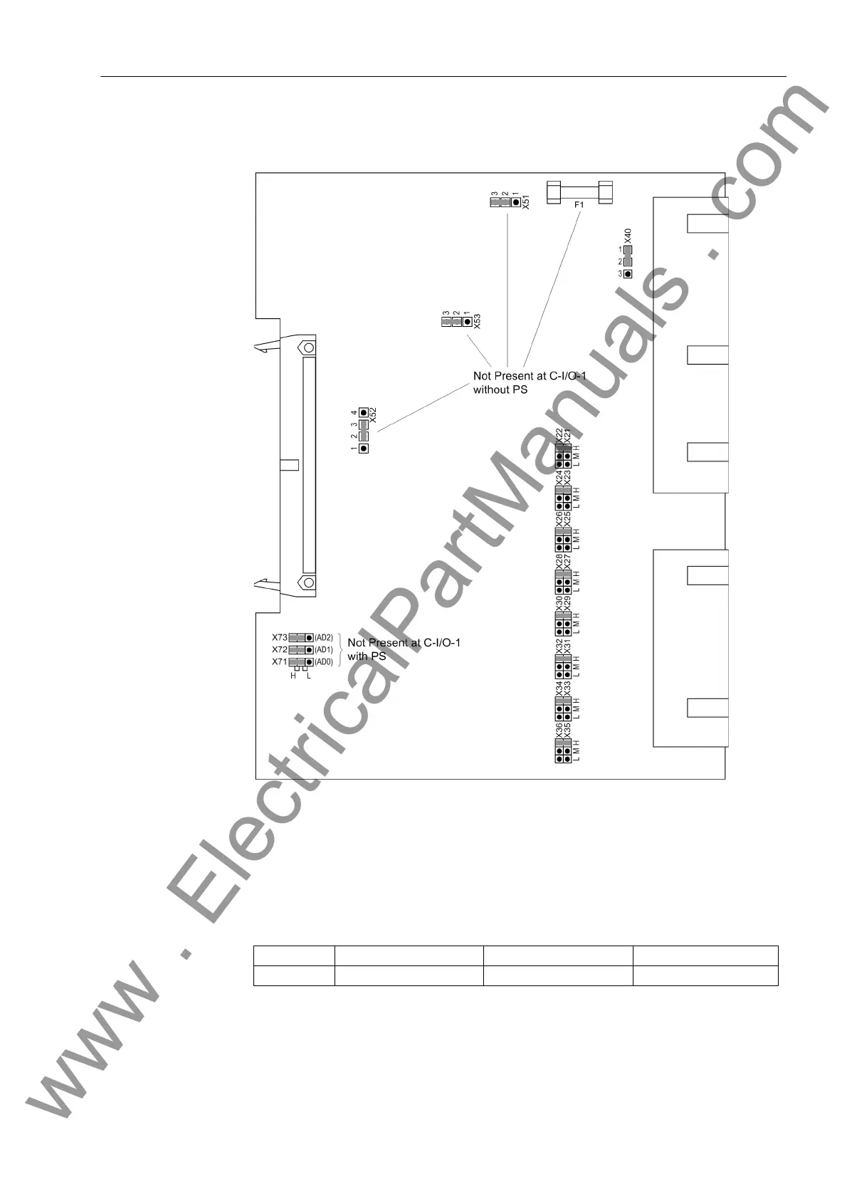
The layout of the input/output board C-I/O-1 is shown in the following Figure.
Figure 3-5 Input/output board C-I/O-1 with representation of the jumper settings required
for the board configuration
In the version 7UM612 , for the Input/Output module C–I/O–1, binary output BO 4 can
be configured as normally open or normally closed (see also overview diagrams in Ap-
pendix A.2).
Table 3-7 Jumper Setting for Relay Contact for Binary Output BO4
Jumper Normally open contactor Normally closed contact Presetting
X40 1–2 2–3 1–2
www . ElectricalPartManuals . com

 Loading...


