3 Mounting and Commissioning
244
7UM61 Manual
C53000-G1176-C127-3
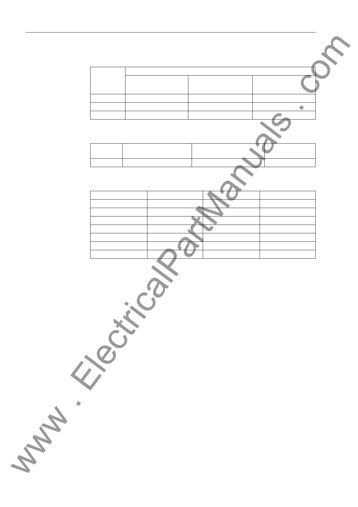
Table 3-4 Jumper setting for nominal voltage of the integrated power supply on the B–
CPU processor PCB for 7UM61.../CC
Table 3-5 Jumper setting for the quiescent state of the life contact on the B–CPU proces-
sor PCB for 7UM61.../CC devices.
Table 3-6 Jumper settings for the control voltages of binary inputs BI1 through BI7 on the
B–CPU processor PCB for 7UM61.../CC
1)
Factory settings for devices with rated power supply voltages 24 VDC to 125 VDC
2)
Factory settings for devices with power supply voltages of 220 VDC to 250 VDC and 115/230
VAC
Jumper Rated voltage
60/110/125 VDC 220/250 VDC
115/230 VAC
24/48 VDC
X51 1–2 2–3 1–2
X52 1–2 and 3–4 2–3 none
X53 1–2 2–3 none
Jumper Open in the quiescent
state
Closed in the quiescent
state
Presetting
X40 1–2 2–3 2–3
Binary Inputs Jumper 19 V Threshold
1)
88 V Threshold
2)
BI1 X21 L H
BI2 X22 L H
BI3 X23 L H
BI4 X24 L H
BI5 X25 L H
BI6 X26 L H
BI7 X27 L H
www . ElectricalPartManuals . com

 Loading...


